|
Home Updates Hydros Cars Engines Contacts Links Contact On The Wire |
How Fast Does It Go Mister?
|
That is one of the questions most often posed, and singularly vitally important as far as we are concerned, as that is what determines results, but it was not always so.
MYRA Rule 16 from 1912. Timekeepers- In power boat racing the taking of the times accurately is of very vital importance, and two or more timekeepers should take all the times with the aid of stop watches of good quality, and if possible synchronized. The times to be taken from the fall of the starter's flag until the boat crosses the finishing line in the prescribed manner. Timekeepers to be distinguished by a black and white rosette. |
|
|
|
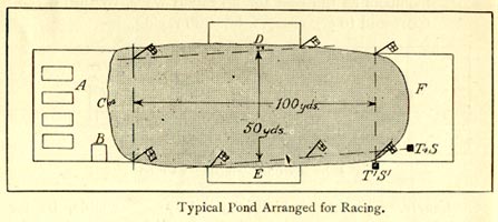
As soon as the concept of comparing one model against another came into being there had to be a means of quantifying the performance, which led to measuring the time taken to complete a set course in a more or less straight line. Simplicity in itself, as you need a starting point and a finishing point and each model is timed from ‘here to there’. With just times being recorded it did not matter how far apart ‘here and there’ were on any given day as it was the same for everyone, but there could be no comparison between different days or venues. This lead to the adoption of a set distance for a ‘course’ (difficult to measure on water), which via some maths jiggery-pokery could be converted into a speed for the run and direct comparison between performance. |
Eventually the ‘circular course’ became the norm, yet through to the late 40s, results for many events would still be declared on time for a run rather than speed. Firstly though, the run has to be timed accurately, which is what numerous enthusiasts over the years have attempted to address.
Simple and accurate.
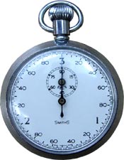
Nothing can be simpler in operation or interpretation than a good old-fashioned mechanical stopwatch. On a straight course, press the button when the model leaves ‘here’ and again when the flagger at the far end waves to indicate the boat has reached ‘there’ and read off the time. Even easier on a circular course as ‘here and ‘there’ are the same place, just separated by a certain number of laps. Times can be read to the nearest 1/5th sec, and accuracy is as good as the reactions and observations of the timekeeper. With the advent of electronic watches, the readings are now in 1/1000ths of a sec, but still subject to pressing the button at exactly the right time and counting the right number of laps. Pretty good by any standards and still in use currently, but modellers by their nature are an ingenious bunch and they have spent untold hours of designing, experiment and construction just in order to remove that human element, and subsequent argument if the timekeeper should ‘get it wrong’ for whatever reason, even if they had ‘got it right’!
In his Smoke Rings editorial in the Model Engineer in August 1939, Percival Marshall raised the whole question of ‘Problems of Model Speed Boat Timing’. He comments ‘that for very many years the problem of really accurate timing has been given the most careful consideration, and various devices for facilitating the observation or recording of very precise limits of time have been devised and tried out’. He goes on to say that ‘hand timing is not really adequate to deal with the high speed attained by many model boats at the present day’. In recognition of this, ‘the MPBA has recommended the closest research into automatic timing devices’.
Remove the human
This is the first step in getting rid of one of the possible sources of error. Still use a conventional stopwatch, but have it operated automatically by the passage of the model around the pylon. Numerous examples of this type of device have been built, but an immediate flaw becomes apparent. The stopwatch does not know when the run has started or when the required number of laps has been completed.
|
|
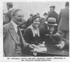
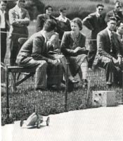
Most of these systems utilised a micro switch on the pole head energising a solenoid that ended up pressing the stopwatch button, but of course it would do that every lap? This requires that some sort of counting mechanism is incorporated that does not turn the watch off until after the required laps, but with races of very different distances and different venues using different line lengths, here is a recipe for complex engineering. Add to this the change from a ½ lap run up to a stated number of laps, and then unlimited laps, perhaps the human touch is not quite such a bad thing? Left: As it was in 1933 at Victoria with Olive Skingley/Cockman and Father In Law Mr Skingley Snr |
Remove the stopwatch
Now this was a bit of lateral thinking by any standards and probably prompted by industrial or scientific applications, where measurement of a trace or tape is relatively common. Still, the other limitations exist, but at least there now exists a permanent record of a run and individual laps. No more claims of ‘they missed a lap’ after a seemingly very fast run. The problem with this system is that there has to be an accurate time base to compare against or a very precise tape speed to allow a measurement to be converted into time or speed. Somehow though this brings the human back into the equation as someone will have to do the measuring or interpretation of the trace. There is also the question of accuracy, which means having the tape speed sufficiently high to be able to measure in the time increments required. Not impossible of course, but probably easier in a laboratory rather than the environment of the pond side.
Enter Electronics and Micro Electronics
There are limiting factors with any mechanical or human controlled system, and that comes back to the speed and accuracy of operating the system. This was hardly a problem at one lap every 6 or so seconds, but as speeds have increased, lap times decreased to just over 1-1/2 seconds, or in the case of cars, less than 1 second. From the moment someone filled a glass bottle with various widgets and sucked all the air out, ever more sophisticated and accurate systems have been possible, if not initially practical. From counting tubes to neon display tubes, through seven segment LED to LCD, stand alone devices have come along in leaps and bounds from the 60s and systems that convert time directly into speed have been around for a while. The range of sensors, triggers and active devices that became available extended the scope of the timing devices even further, allowing continuing readouts of speed.
|
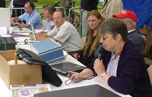
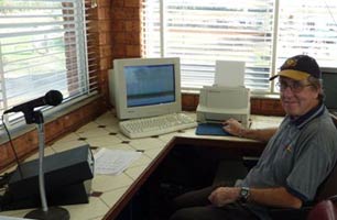
It was the arrival of the PC and later the laptop that completed the picture and created totally integrated timing systems that can record continuous lap times of well under 1 second, and speeds in excess of 250mph simultaneously, print it all out almost instantaneously and even assemble a series of runs into rank order. One thing all this wizardry still can’t manage is to decide when a run starts, and for that we still need the human being, and sticking a hand in the air or pressing a button is still as valid now as it ever was, mind you, you have to be quick! Right: As it is in 2010 at the Sydney track |
|
The Hardware
In Percival Marshall’s 1939 ME editorial, he acknowledged that ‘at present several designs are successfully employed’ and went on to describe some of the principles involved. He added a complication that goes right back to the start of the article in that the weight of the boat and the speed would create a differing amount of stretch in the line then used so that no two boats would ever travel the same distance for a given number of laps. Not a problem with a steel wire thankfully. This is not a treatise on timing, but in typical OTW style has been prompted by what has been recorded and what has survived. Modellers being what they are, were more than equal to the task, producing some superbly engineered timers, and so here is a look at some of the marvellous devices they have come up with.
|
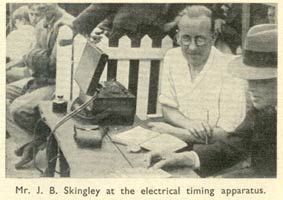
Jack Skingley of the Victoria Club built the earliest we are aware of, probably in the late 1920s. This combined timing with some sort of tape system; all being worked by a micro switch on the pole head. Several pictures exist of it in use at the lake and it was last heard of in the possession of Olive Cockman, Jack’s widow, but it has since vanished. Right; Jack Skingley seen here at Victoria in 1938 |
|
|
|
|
More details are known of an Electro-mechanical device built by J. Turner of the South London Club in the early 1930s. This rather set the trend for many that were to follow as it combined a lap counter, a conventional stopwatch activated by a solenoid and a switch on the pole. It won the Electrical Industries prize as the best electrical exhibit at the 1932 ME Exhibition and was described in the ME for Oct 13th 1932. |
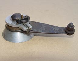
In the mid 1930s, Jack Orme of the Chesterfield ME Society produced a very compact device that used a spring-loaded arm to actuate the stopwatch with the solenoid acting as a catch this time, but the laps had to be counted and the arm reset by hand. Edgar Westbury as ‘Artificer’ described this in 1936 and added an alternative design with a solenoid activating the stopwatch.
|
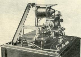
A Mr Ivison provided the first very detailed account of a tape type machine in 1939. This used a paper tape running at a precise speed under the two recording pens, one being worked by solenoid from a redundant alarm clock that gave 100 pulses per minute off the escape wheel and the other via the pole head. Mr Ivison was not a competitor, but the concept fascinated him enough to produce this remarkable device. |
|
|
|
|
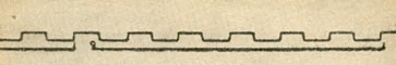
Interpreting the trace on any tape-based machine is where the problems really start though. |
Firstly, the run will not conveniently coincide with a time pulse, so the distance between the start of the lap and the next pulse has to be measured, guestimated, or compared with a scale and then added to the lap time. Secondly, the complete number of time base pulses have to be counted and thirdly, the run will not end at an exact pulse, so the additional fraction will again have to be measured and added to the total. The total number of pulses during the run plus the bits, and some mathematics gave the exact time of the run. Plenty of room for error and misinterpretation here compared with a stopwatch and eyeglass.
|
Something that will be apparent already is that each device described gives a time for a run so that tables that convert elapsed time into speed will have to be prepared for every race distance. This requires a lot of mathematics and tabulating, as the calculations must be carried out for every time interval over the possible speed and distance ranges and runs to several pages, even at 1/5th second intervals. Right: Early American system with solenoid operated stopwatch and lights to count laps |
|
In 1944, Gerry Buck of the North Staffs club built a lovely device that was small enough to fit in his jacket pocket, as befitted a Jeweller and model engineer. The heart of it was a 10 second sweep stopwatch operated again by an arm and solenoid could be read to 1/10th second intervals. The stopping of the watch was controlled by a plunger operating on a series of drilled discs indexed each lap by another connection to the swinging arm. A later version was even more compact with a lap counter that could be set for a wide range of laps. A chart for ¼ mile speeds calculated between 8 and 42 seconds was attached inside the lid of the 8inch by 4 inch by 1 ¼ inch wooden box that contained the timer. The pole head that Gerry built and that was shown in the later ME articles turned up at a Gildings sale recently.
 |
 |
 |
| Original 1944 design | As it is now with new lap counter | 2nd version of pole head |
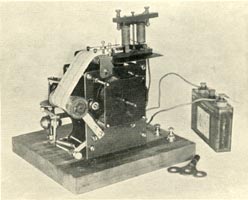
The Eaton Bray Model Sportsdrome opened in 1945, and for its first full season of tethered car meetings in 1946 unveiled their version of a time base tape timing system. Peter Hunt, technical editor of Aeromodeller and early exponent of radio control was responsible for developing this device and describing it in Model Cars. The most obvious difference was that this timer was not triggered by switches of any sort on the pole head, but by a photoelectric cell outside the circle.
|
Even more remarkable was that there could be up to 10 tapes and undulators running side by side at the same time. All the tapes were driven from one synchronous motor and all the undulators from one ½ second chronometer. Each half-second the pen would move in one direction and every time the light beam was broken it would move in the opposite direction. Right: The Eaton Bray system with 5 tapes set up for recording |
|
|
|
With the tape moving at just over ¾ of an inch per second, again someone would have to measure, the distance between the lap mark and the first half second, count all the complete half seconds and then add on the extra bit at the end. Even at this stage, Mr Hunt had identified a problem with remote sensing, that is still causing difficulties today, and that is actually getting the model to trigger the system reliably. A car does at least arrive at exactly the same place each lap, but a boat is too far from anything solid and reflections from the water can play havoc, while speed planes are by definition off the ground by varying amounts. Left: Photo-electric sensor in use at Eaton Bray |
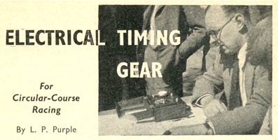
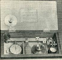
With the reforming of the Blackheath Club after the second war it was considered that some form of automatic timing device would be needed if the club were to host MPBA regattas. Les Purple, owner of the delightfully named hydroplane ‘Dopey’, set about the task, working on the same principles that had been established before. The lap counter, made by John Benson, was advanced by one solenoid, while a second activated the mechanical stopwatch. The whole thing was simple and compact and housed in an exceptionally well-constructed wooden case, built by fellow club member Mr Liffen. So well made was it that the lap counter would advance several laps at once, even though the power supply was only 6V from a motorcycle battery. With this problem sorted, it became a very reliable and portable device and with a simple switch added to the pole line could accommodate different numbers of ‘run up’ laps. It served the club until hydroplane racing ceased in the mid 1970s.
 |
 |
 |
Model Cars for May 1950, published an article by Carl Wainwright describing a simplified version of the Gerry Buck timer that he constructed for the Leicester Mini Car Club. Gerry and Carl were well acquainted, yet Carl considered some of the elements in the original were over engineered.
|
|
One solenoid still operated a swinging arm that advanced a ratchet wheel, actually a slitting saw blade, and also operated the stopwatch. The need for differing lap numbers could be accommodated by separate discs that attached to the ratchet wheel. He also mentioned a second timer that used fellow club member and racing driver Bob Gerard’s three-second stopwatch that could be read to a remarkable degree of accuracy. Left: Carl Wainwright's version of the 'Gerry Buck design' |
|
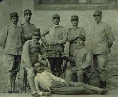
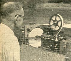
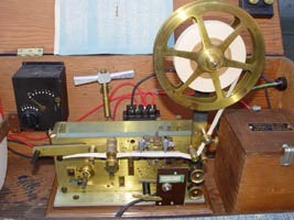
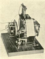
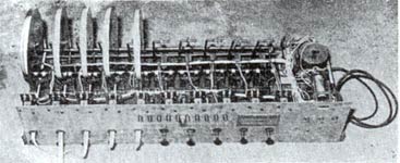
If the previous three devices were notable for their compactness and portability, this certainly was not true of the system that featured in the ME in Nov 1950, built by Leslie Raxworthy of the scientific section of the North London Society of Model Engineers. The whole system was based on an Italian portable Morse telegraphy unit dating back to the 19th Century, made by PioPion in Milan. |
|
 |
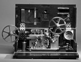 |
This was a clockwork tape device with a standard undulator and pen. Firstly the undulator was rewound to drive two pens, but in only one direction. Next there had to be the addition of some form of time base, which was accomplished by the addition of a Venner clock pulsing every half-second operating one of the pens. A micro-switch on the pole operated the second pen. |
The pulse clock was also connected to a Synchronome slave movement on a large dial showing elapsed time at ½ second intervals, which could also be set to run independently of the timer. The lap counter was an entirely separate electro mechanical device that showed the laps covered and could be set to switch off the main timer after the required number of laps. Each run was recorded as a continuous line with a minute gap at the end of each lap. Alongside this were the ½ second marks and spaces from the pulse clock, which could be counted and measured to give the time of the run. Again, reference to tables was required to convert this into speed. The whole device was built into a wooden case some 2 feet long by 1 foot wide and deep, certainly by far the largest and least portable of all the systems so far discovered.
 |
 |
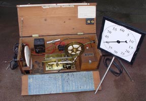 |
| In use at Victoria in 1951 | System restored and rewired 2009 | Complete system with new 'visual indicator' |
The shear size of the NLSME device prompted Gerry Buck to write to the Model Engineer, offering a prize of 2 guineas for the best timer based on his own 1944 design. The directors of ME decided to offer a further 5 guinea prize for the best timer of any design, and followed it up with a series of rules of which the first two are worth quoting. 1) The mechanism must not be over pretentious in design and be of such proportions as to render it readily portable. 2) The design must be strictly practicable and represented by working drawings. Closing date for entries was Dec 1st 1951. There followed a series of drawings and descriptions by ETW, mostly reprinted from his 1936 article of what had gone before. There seems to be no further mention of the venture, so perhaps lack of interest or ideas scuppered this competition?
|
Effective though most of these electro mechanical devices were, thoughts were turning to electrical systems, but it was the arrival of low voltage electronics that produced a bewildering array of ever more sophisticated and accurate machines. There were still those that stuck with what they knew though, including Jimmy Jones who build his own timer around 1961-62 for use by the newly formed power boat section of the Birkenhead Club. Jimmy Jones on right demonstrates his timer to 'Doc' English |
|
By his own admission he based his timer on the designs published in Model Engineer and there were marked similarities between his and those of Gerry Buck and Carl Wainwright, even to the use of a slitting saw blade for the ratchet wheel and interchangeable discs for differing numbers of laps. At 11inches x 7inches Jimmy’s timer was significantly larger than Gerry Buck’s, but still eminently portable, apart from the six-volt battery from his ‘old Ford car’ that provided power for the device. He explained in an article in ME in November 1962 how he had overcome the same problem that many others have faced, and continue to experience with switching at the pole head. Any contacts have to be positive enough so that there is only one pulse, long enough to energise or trigger the timer, yet switch at the same time every lap. As speeds increased, so inaccuracies in this area become more damaging to the accuracy of the system as a whole.
Although opposite sides of the country there were close connections between Birkenhead on the Wirral and the Heaton Club up in the North East so it was no surprise that they produced a near identical device to that of Jimmy’s.
|
The timer was used at the Paddy Freeman’s Park lake for their hydroplane
events for several seasons. This was probably the most accurate of the devices using mechanical
stopwatches, as the Smiths watch fitted had a 3 second sweep hand so that the
dial could be read to a 1/100th of a second. Right: Timer built by members of the Heaton
Club |
|
|
|
|
|
Vic Collins brought this whole idea up to date when he produced a superbly engineered electro-mechanical system that was in use by the Model Hydroplane Club until very recently. This used the same basic principles as many of the earlier devices, but allied to the inherent accuracy of a modern electronic stopwatch. |
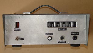
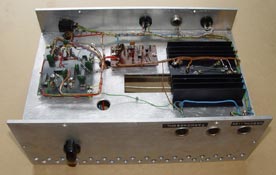
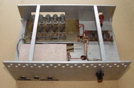
All these devices can best be described as electro-mechanical with all the attendant problems, yet a ‘look inside’ will reveal how they work. The more modern electronic or micro electronic systems come under the ‘box of gubbins’ category as was discovered when the cover was taken off the unit built by Gunther Stranzinger. Looking at the complexity of the electronics, it is probably no coincidence that he worked for Bosch. This is essentially a very large electronic stopwatch, displaying time on a series of neon tubes, with additional circuitry that can drive a large speedometer so that the competitor can see their approximate speed. It also has the facility to be triggered by the competitor rather than the timekeeper reacting to a signal (sometimes missed). If the connections can ever be figured out, then it is quite likely that it could still be in full working order.
 |
 |
 |
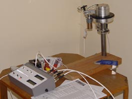
The micro electronic devices now manufactured on a semi-commercial basis are beyond the realms of model engineering, and inevitably do not come cheap, even if they can be obtained. To this end, the late Tom Clement of the Heaton Club had been involved in producing a very effective electronic system that is now in regular use at British regattas. This can time 5 or 10 laps and gives a continuous readout of speed on a large dial, both for a 100m lap and 100 yd lap. Whether one of the integrated systems would work on the expanses of water that boats use is open to question, but it does not matter whether it is cars, boats or planes, it still needs a physical action to indicate when the timed run starts, so happily, the human is not entirely redundant in the process.
 |
 |
 |
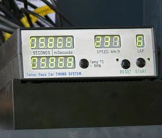
| System currently in use in the UK | Australian system with time & speed | Carlo Fontanesi's timer in use at Amiens |
Strangely though, tethered hydroplanes are the only discipline that still requires three independent times for a record to be recognised, rather than accepting what the readout from a machine says, even though it is calculated that an electronic system is between 20 and 100 times more accurate than manual timing, especially at high speeds? Even more remarkable then is that at several venues a hand-wielded stopwatch is still the norm, even if it is now not a mechanical one. Now what is needed is a device that………..mmm, isn’t this where we started?
Thanks go to Jim Free, Terry Everitt, Tony Collins, late Tom Clement, Stuart Robinson, Norman Lara, Norman Phelps, Alec Graham and Kent Lund, for help, information, photographs and loan of surviving hardware.
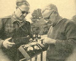
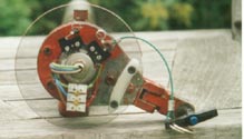
Update Sept 2011-The mystery box
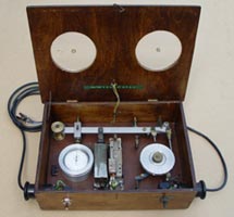
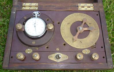
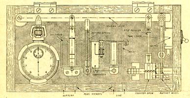
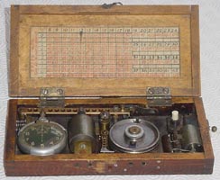
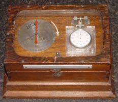
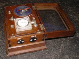
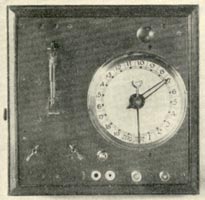
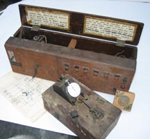
When Mike Rose eventually opened the wooden box that he had inherited from his late father John, it revealed this wonderful tethered hydroplane timing system, similar in layout to the Blackheath one above, but significantly different in construction. Study of the photos and conversation with Antony Rose has enabled us to speculate as to how it functioned. It must be remembered that in the era this timer was made, boats were restricted as to the 'run in' allowed before timing commenced. The dial would presumably be set with either the run in or laps to be counted. The single coil advances the dial one click per lap and underneath the ratchet appears to be some kind of arrangement of insulation and contacts that are connected to the double coil with an armature that will swing both ways moving the forked lever seen at 10 o'clock on the watch. This would operate a side mounted switch on the stopwatch, moving it one way at the start of the run when the coils were energised in one direction and then back at the end of the timed laps when the current was reversed to stop the watch. Antony has worked out that the watch fitted, although a 1/100th second model, was not the original and would not work with this system.
|
|
|
|
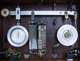
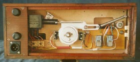
Battery and pole connections below. Lap dial and stopwatch above. The fork that would operate the stopwatch can be seen to the upper left side of the watch. |
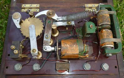
Single coil advances dial one tooth per lap via the ratchet and pawl. Double coil moves armature up or down depending on current direction from contacts to the left under count wheel. Adjusting screw stops the ratchet from advancing more than 1 'lap' per pulse |
There was a suggestion that this timer might have originated from the Bournville club, but as yet it has not been possible to establish the accuracy of this. From conversations and photos, we can establish where it is unlikely to have come from, and at present it is unique in requiring a side action stopwatch rather than all the others which have some method of pressing a conventional crown button.
Thanks to Mike Rose for photos and information.
©copyrightOTW2010
 .
.