|
Home Updates Hydros Cars Engines Contacts Links ←Previous Next→ Contact On The Wire |
|
|
John Goodall Building and racing retro tethered cars |
Harry Howlett inspired Oliver
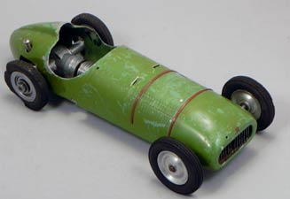
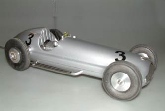
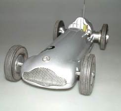
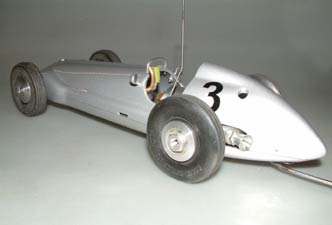
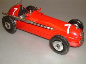
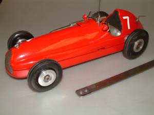
The Oliver cars were all designed by Harry Howlett and all drawings from the factory acknowledge this. Although the production cars are best described as semi-scale, Harry had his own version of each to which he added huge amounts of detail, louvres, exhausts, mirrors, windscreens, cockpit detail and more. As John Goodall describes below, he has applied a similar treatment to a standard version of the Oliver Mercedes.
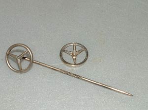
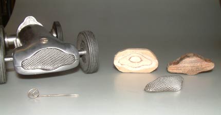
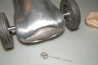
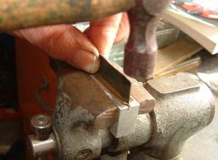
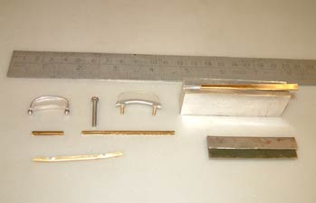
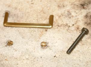
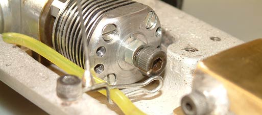
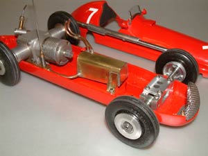
This is the Mercedes/Redfin twin shaft I purchased at Buckminster, which I have been doing some work on as shown. I decided to add front suspension and some detail and thought others might be interested in how I approached this. I obtained a Mercedes pin badge off ebay for the Mercedes motif on the nose, one cost £1.50 and the other £2.99 I think, including postage. You could not make them for that and the finish is good too? The 0.04” diameter wire was straightened with pliers and then threaded 14BA which is just about the correct start size. I shall make a nut to secure it in position after painting. The front suspension is again 0.032” spring steel with riveted on stub axles as was described for the ZN car. These were left longer than on the ZN car so that the slots already cut in the top half were utilised to support the axle from road shocks. The spring steel was cut using a Dremel cutting disc and drilled using Cobalt drills as described for the ZN.
 |
 |
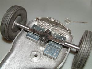 |
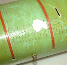
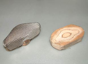
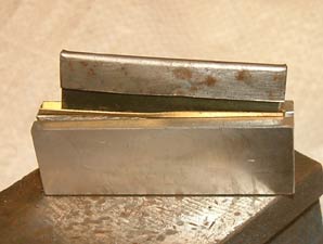
The grill was made from SS mesh I had in stock and I made a male former to slightly less in size than the aperture shape with which to bend the mesh over, but quickly found that the curvature was not maintained due to spring back. I then made a female block gouged out using a chisel to match the concave curvature and this helped greatly in maintaining the shape. The two parts are clamped in the vice which effectively forms the curvature on the mesh and then the edges are carefully turned over with light hammer blows leaving a broader strip at the base so it can be fixed to the body as shown. I pierced the holes using a scriber to start and increased the size with an awl. I thought drilling might be awkward and possibly dangerous, as the edges are very sharp and can cut fingers?
 |
 |
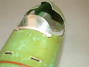
The detail added included dummy windscreen, rear view mirrors and an exhaust pipe and I shall finish paint in Mercedes Silver stove enamel with red or black Vinyl racing numbers. These numerals are available on ebay fairly cheaply and come with multiples of each type of number on one sheet. Great care is needed if applying these stickers dry as once positioned and in contact with the surface they will not come off, or move. Wetting the surface with a slightly detergent solution to give some slideability is advised by some vinyl users. This can be squeegeed out using a credit card, or similar plastic padding applicator. I have used these on vintage motorcycle tanks and when clear lacquered on top are far better and more durable than transfers which can lift, especially in the presence of petrol.
 |
 |
 |
An idea for making scale like dummy windscreens.
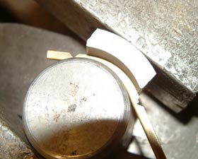
I have been trying to make windscreen frames for some of my Oliver scale type bodies and others for some time without real satisfaction. I found it difficult to bend a "U" shape section of small enough size to look realistic when completed. I decided to try and make a simple press tool from a piece of alloy block in the scrap tray and milled a narrow slot that was just slightly wider than the combined thickness of the screen made from polycarbonate (PC) and the two sides of the "U" shape section made in brass strip. It was long enough to bend up the longest length of section I needed. I initially cut a piece of mild steel to use as a punch, the same thickness was as the PC. A piece of 0.015" brass shim I had was cut into suitable strips to adequately form the finished section and again long enough for the length required. The "U" section came out as 1.5 X 2.5 mm overall.
 |
 |
 |
|
Forming block set in
vice ready to commence bending |
I strengthened the
punch as shown here with first forming of the brass |
Bending the frame using suitable formers |
The brass strip was then placed centrally over the slot who's upper edges had been slightly rounded to guide the brass into the slot as it is formed. I then tapped the top of the punch with a small hammer and gradually worked back along the full length until the bottom of the slot was contacted. Leave a short piece extending over the block edge so that you can prise the "U" section out of the slot otherwise it is difficult to remove. You can finish off the overhung bit by turning it end for end and doing the same again. I then dressed off the uneven top edges of the "u" section with a fine file using the block to hold the section, don't be tempted to hold it in the vice, otherwise you will flatten it. You now have the material to make your frame up as needed.
|
|
The first
one I made was for the Walshaw BRM I obtained recently:
OTW aside. This car was lurking on the floor at the Gildings auction in 2014, described as 'Early tethered car, incomplete'. It passed entirely unnoticed and dismissed by all those viewing and was eventually knocked down for a modest fee to an American bidder who even then reckoned that he had paid far too much for it with shipping and import duty. That is until the true origins of the car were recognised. It transpired that it was a BRM model produced by G.V. Walshaw down in Dorset with an ERE twinshaft motor and tyres supplied by none other than that great modeller Henri Baigent. The car was illustrated and described in Model Maker in Feb 1951, available as a kit of parts for the builder to drill and fit, the same kit with all the machining done or a fully assembled version for £12-0-0. It has now returned to the UK. |
|
The overall size of the windscreen was dictated by two existing holes in the body top. I took the section and softened it by heating to dull red and allowing to cool and then found I could bend it by finger power to conform to the body top curved shape. I also added a slight curvature in plan. Next how to secure to the body? I took two countersunk head brass 8BA screws 3/8" long and dropped them into drilled holes into a furnace insulation brick purloined from an old closing power station. I have just a few if any one would like one? The holes are spaced as were the body top holes. Then the section and screw heads are cleaned and fluxed and the section placed on top of the screw heads and propped with another block of insulation material, at the rake angle thought appropriate. I then silver soldered carefully just adding enough silver solder to get a sound joint and no more. You really do not want to need a filing operation to remove excess silver solder, the parts are too delicate for this, so be warned. From here I clean with a fibre glass pencil after a soak in water to soften the flux. It can then be painted, nickel plated or however you wish to finish it. Right: The BRM screen as finished |
|
|
|
I tried to use wiped solder on the BRM frame to give a silvery type of finish, but found the mass of metal that small, that heat applied was not retained long enough to wipe the solder to obtain a good coverage, but it is just about acceptable and looks worn enough to match the rest of the poorly treated body with distortion damage causing badly flaking paint. I was tempted to repaint it, but found some of the applied detail was actually in the paint layer and did not appear on the body material, which surprised me greatly, I have to say. This raised a question in my mind as to how this was done when it was made originally? I can only conclude something like a dress-makers pattern wheel was made and instead of spikes with several bent sections added radially so that when rolled along, it marked the paint surface with the shape of the louvres in a row. Can you think of any other better solution? Left: BRM dummy louvres not evident below paint, note tether fixing split pin and plastic strip bonnet straps? |
I made another screen for the ex Olly Monk Mercedes, not being satisfied with my first attempt. For this I had made up an alloy frame from welding rod and screwed the two ends with 10BA threads for nuts to secure to the drilled holes in the body top. The PC screen was made from a piece of the same thickness as the diameter of the welding rod and a half round groove filed around the sides and top to secure it in the bent section. It held OK, but would not rake backwards as it should. The other problem was it damaged the paint finish of the body. The new frame was again similar to the BRM version, but smaller and it worked OK, but having got this far, I thought why not go the whole hog and make one with mitred joints and upright side legs to look more like the original full size version. I show as far as I have got with this, it is still to be assembled and silver soldered. I mitred the joints with a square needle file again held in the bending block, taking care not to cut all the way through and so leaving enough material to hold the vertical legs prior to silver soldering. If you try to make this from three pieces it will be virtually impossible to hold and or jig it for this operation. I softened the brass and bent the legs up and again later curved the bottom portion to match the body top. I shall probably get this nickel-plated.
 |
 |
|
The first
Mercedes
screen and the first attempt, showing tools plus 6BA screw |
The silver soldering block with screws and Mercedes frame ready for soldering, a 6BA screw for scale |
A simple fuel 'cut-off device
The BM FNO set open.
I recently repatriated a few cars from a tether car enthusiast and friend in USA John Lorenz, and was later offered two Swedish built cars which I again brought to the UK, basically because of my liking for and interest in the Swedish scene. One car was what I initially thought was a prototype Slabang, but this was not so. A good friend in Sweden, Kjell Erik Odelius, told me the car was built by Bo (Bossi) Martens and that he had seen a Slabang at an event and went home and built his own version powered by a SuperTigre diesel converted into twin shaft configuration. The car is longer and a lot slimmer in height than the Slabang, with added features that spiked my interest. He went on to build four or five more of his own twinshaft engines all different I believe, and usually with his own car bodies. Lennart Helander sold this car to JL somewhere around 2000. The other car was a Komet powered MRO "Model Race Orebro" as best I can decipher and again because of its origin it had to come to the UK, as it was conceived at or near the track I have run most on, at Orebro in Sweden.
|
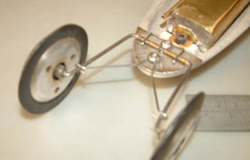
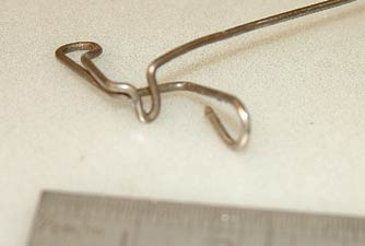
Two things interested me in the BM car apart from the engine, the front suspension which is similar to, but not the same as that on the Slabang. In fact, like that which follows, the suspension idea can be used in your own cars as it lends itself to fairly easy home construction and serves the purpose very well. I intend to use the concept in future. The most notable and impressive device however for me which I will describe now was the "Fuel Nip off" (FNO) which was bent up in a single piece of piano wire 0.040" (1mm) diameter. A brilliantly simple design, I would have been proud to conceive. I have been looking for an easily made and also cheap to make fuel cut off device for some years now and have made a few Swedish derived designs, Oliver and Healy types, all a lot more difficult and time consuming to make than this one. Right: BM front suspension |
|
|
|
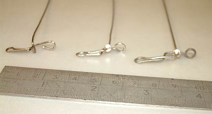
I had a couple of attempts to make a replica of the one fitted to this BM car and failed due to the very tight bend which forms the latch to hold the spring open. I also found it was not ideally aligned with the latch arm and tended to stop on the vertical leg not the top leg as I felt it should. So I tried to twist it through 90 degrees to horizontal to ledge on the horizontal leg and felt it give or weaken towards ultimate fracture, so stopped twisting at that point. I could not get the bend tight enough and in the correct place either in my own attempts and thinking wider if I could devise a slightly different approach came up with a soldered on brass cone turned up in the lathe to act as the stop as per Oliver. This gets over the difficult bending problem and is adjustable for nip too, but the biggest advantage is it becomes a lot more easy to set to on, as all that is needed is to lift the knock off arm upwards and the cone slides over the horizontal fixing/stop leg latching it in place. A lot easier to set than the original I can assure you. Left: The original FNO device |
It can be biased towards the latch by a twist after bending up. Keep it as compact as you can, because the spring nip decreases with increased length of the operating legs as I discovered. They are that cheap to make, you can experiment yourself to get a satisfactory solution as I did. I positioned a 12 inch rule in the photographs to give you the scale and dimensions which are not that critical, except as mentioned.
|
|
The FNO has other advantages in that it does not leak, does not seize up solid like Oliver types do when sparsely used and will not reset. The down sides are it might need more regular replacement of the fuel tube in order to give better reliability, I always store with "Nip Off" open to prevent tube squash. One other downside is the operating arm swings through approximately 20 degrees when set to the off position, this needs accommodating in your installation to prevent excess friction.
A
lot can be made from one length of piano wire and I have gone up to
0.048" (1.2mm)diameter piano wire to give a little more spring action and
grip on the fuel tube. You can bend up a loop at the upper end to
prevent injury and a loop will pass through a slot more easily too
than a ball, and you can grip it more easily with oily fingers. |
I now use Tygon fuel tube widely advertised on eBay. This is made by "Saint Gobain" the glass firm that arch model car enthusiast Miguel De Rancougne worked for. Miguel had a very important position in World Sales too I believe, another late lamented friend.
|
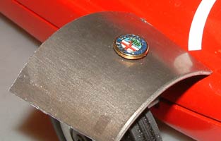
Harry Howlett treatment of an Oliver Alfa Romeo Harry Howlett was the inspiration for the range of semi scale cars produced by the Olivers. Hundreds of originals and replicas have been made over the years, but very few have any level of detailing added that made Harry's cars so outstanding. John Goodall follows in the tradition of Howlett by adding significant extra finishing touches to his Oliver cars, as demonstrated by the Mercedes at the top of this page. His latest version is an Alfa Romeo with full front suspension from a Redfin and an original Oliver Tiger MkII. As with the Mercedes, a final touch is the enamelled Alfa badge. |
|
However, as John points out, the disadvantage of adding such details is that they do not respond well to the interaction of the stopping brush that can wipe most of them off in a single swipe. Perhaps that is why a carefully wielded cloth or cap was the preferred method of stopping cars in 'the good old days'.
 |
 |
 |
| Exhaust with heat guard | MkII Tiger and Redfin suspension | Mirrors and flyscreen |
©copyrightJohnGoodall2021