|
Home Updates Hydros Cars Engines Contacts Links Contact On The Wire |
John Goodall's 'New Oliver style' Models
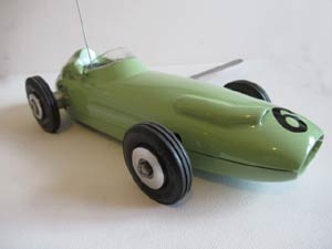
The 1957 Vanwall
On a Thursday afternoon in late 1957 I passed my motorcycle Driving Test, just two days prior to the British GP taking place at the Aintree Circuit near Liverpool. I was serving an apprenticeship in mechanical engineering at FNF in Burton upon Trent and asked a fellow apprentice friend Peter Sherratt if he fancied a ride on the back of my few weeks old Triumph Tiger Cub to go to Aintree for the GP, he jumped at it being even keener than I was.
We travelled up in fairly good weather, parked the bike and found a spot to view the race in a U shaped part of the track between Cottage and Country corners. The entry list had all the top names entered from the great Juan Manuel Fangio, Peter Collins, Mike Hawthorn and lots of British drivers including Stirling Moss, Tony Brooks and Stuart Lewis Evans all three in the new Vanwall, with Moss being quickest in practice. In the race Moss was doing very well until the 51st lap when he pulled into the pits with a problem and the team called in Tony Brooks and Moss took over his car, now well down the field. Moss drove superbly well overtaking all other drivers to win after 90 laps of the 3 mile circuit, with Luigi Musso second and Mike Hawthorn third. This was the first British car and driver combination since Henry Seagrave driving a Sunbeam in 1927 to win a British GP in a British car. That is why the Vanwall still means so much to me.
Ian Harper took over The Oliver model car body patterns from Paul Ironmonger at the SAM 35 Octoberfest in 2004 and later asked me to join in his venture and I said I would help in any way I could, which I was very happy to do. I had always felt the Oliver car range lacked British content and balance with three Italian cars and only one British car, so I suggested to Ian we should add the 1957 Vanwall to the range and Ian agreed. So I made pine patterns and had the first batch of castings produced in Ian’s local foundry.
 |
 |
| Pine patterns ready for the foundry | |
The Vanwall castings after this initial batch of eight, will join all the other bodies available from Ian from now on and align with their prices. My first Vanwall won the inaugural Redfin Trophy event, but built on the Redfin chassis with a wooden body was eyeball scale only. The new Oliver version is much more accurate in every aspect and available from me on Market Place.
.jpg) |
.jpg) |
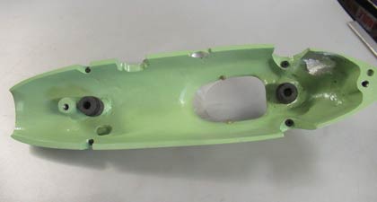
| Castings fettled and joined | |
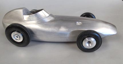
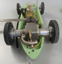
I commenced building the new prototype and matched and joined the two body half’s secured with M4 CSK socket head screws as the first step and then cleaning up by hand filing the casting exterior and joint line before final polishing with abrasive tape to my satisfaction. I intended adding both front and rear suspension to cope with the Buckminster track condition, so I next concentrated on the motor platform for a new Redfin Twin Shaft engine I had in stock and its brass hinge at the forward part of the mount. This 1/8" Dural mount is controlled by a spring damper unit filled with oil and found on Ebay. The copious space inside the Vanwall body makes this an easier task to fit in than on either of the stable mate Ferrari, or particularly the Mercedes cars I had previously built with the rear suspension idea pioneered by Ian Wingfield. The control arm is taller and gives better leverage restraint allowed by this extra space. The travel is limited at front and rear by drilling into the body axle cut outs above both axles and inserting a plug of "O" ring rubber to arrest movement, this works well too and stops metal to metal noise at full deflection. The mount was extended at the rear end to support a Mike Francies 3D printed 'curly carb', which fits neatly inside the body, drawing clean air without unsightly body cut outs which I hate on a scale car.
.jpg) |
.jpg) |
| How all the 'works' fit inside with just the cut off protruding | |
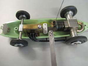
The front suspension utilised a milled alloy trailing swinging arm pivoted at its forward end, and this time controlled by anti vibration rubber spring damper units which are self damping, made for Quad copters/drones Ian suggested using them and I have to say they work very well. The smallest can be pushed inside the larger ones to stiffen up if needed which is what I did with a small unit placed below the arm to control the rebound. The axles on both front and rear suspension pivots are made from 1/8" diameter SS and held in place with grub screws to prevent sideways movement on the move.
.jpg) |
.jpg) |
.jpg) |
| Brass trunnion blocks | 3D printed 'curly carb' | Internal layout of suspension |
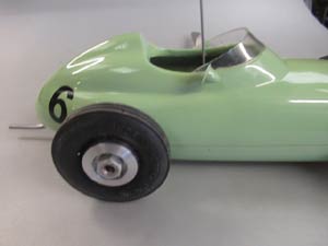
In practise the car is very stable on the track where it ran for the first time at the SAM35 Redfin Trophy event on 14th June 2025. The body is a little on the heavy side, but this seems to help the stability. Standard Redfin wheels and tyres are used front and rear. I did find it necessary to mill out below the engine mount rear end to give maximum ground clearance.
 |
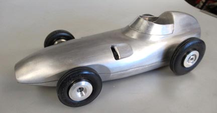 |
| On its wheels and ready for detail finishing | |
I
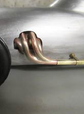
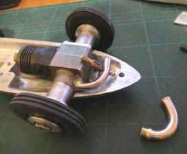
made the four branch exhaust from solid 3/16" diameter copper rod bending as shown and then joining with hand filed contoured tapers and flutes to give a good fit for silver soldering at the tailpipe junction. If you are adept enough you could use a round end 3/16" diameter end mill to rout these. One of the centre pair of pipes is left longer and a recess turned on it to locate the brass tailpipe, this obviously has to be done before bending. Forward Planning! Is sometimes essential! A 3/16" OD brass tube was cut and bent to follow the body curve fairly closely as on the full size. Two securing exhaust pipe brackets were made from brass close fitting turned narrow rings with 8BA brass screws silver soldered to them. These were fixed to the body through two holes drilled and counter bored inside to accept 8BA nuts. The lower end of the four branch exhaust had a 1/32" thick brass plate silver soldered to join the four ends and to provide a stop inside the body, where a cut out was drilled and filed for the tapered end to pass closely through. This serves to hold the exhaust forward end with no movement with the four branch resting on top of a sloping ramp filed from the slot rewards. The whole exhaust was nickel plated after a trial assembly.
.jpg) |
.jpg) |
| Superbly modelled four branch manifold before plating | |
The fuel tank was made from brass sheet and copper pipe for feed and forward facing vent. A screwed filler was made and soldered into a hole cut in the nose of the tank. Three brass mounting brackets are soldered on and used to raise the tank to align with the jet centre. One of my last Redfin cut offs was modified using the obligatory larger brass latch cone and next higher wire gauge to prevent premature self tripping.
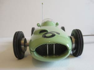
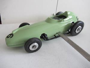
The tether arm was made from SS and attached to the cast in boss in the bottom half or chassis in the usual Oliver fashion with two socket head screws. I added a dummy radiator grill set back inside the nose to hide the front suspension and trapped under it.
.jpg) |
-(1).jpg) |
| Arrangement of Csk screws in pan | Prototype and finished model as run at Retrofest |
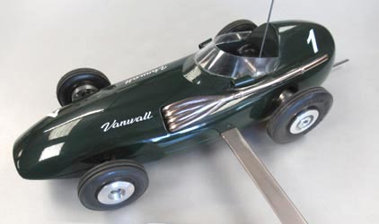
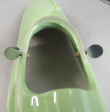
The windscreen like the four branch exhaust was intended to be available from me using 3D printing along with the body castings to help the builder, but so far the commercial attempts over six months have not proved satisfactory, so I found some clear soft and flexible plastic sheet 1mm thick on Ebay and cut this using scissors to suit the cockpit edge shape and glued in place after painting using ultra violet curing clear glue named "Quick Fix", which cures in about three seconds only. It is best to apply this to the joint area and hold the top of the screen in a U shape to match the cockpit outline with upper edges naturally sloping inwards to align with the back rest upwards taper with drafting tape which peels off easily later, sit the screen down with the rear ends aligning with the cockpit profile and tape to hold if needed and cure with the UV device supplied all less than £10 with most of it still left. I had the body stove enamelled in British Racing Green and this glue holds the screen rigidly well on these stove enamelled surfaces with no damage at all, even after using the stop brush. I believe the flexible plastic helps in preventing damage as a bonus. The first car windscreen I made five years ago from polycarbonate did not survive the brush cut out stop, but that was epoxy glued on to acrylic spray can paint.
 |
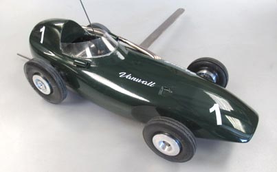 |
| The finished car looks superb, especially running on the track | |
I found a company on Ebay who made me two sets of 'Vanwall' white Vinyl self adhesive stickers 40mm long O/A and 10mm high for less than £12, so less than £6 per car, the company was fab_beauty_accessories, and they did a fast turn round as well. This completed the car with some white vinyl racing numbers added, again available cheaply on Ebay.
Oliver BRM P25
When Ian Harper obtained the Oliver model car body patterns there seemed to be two Ferrari patterns, one made in aluminium and one made in balsa wood, the latter differing only in having no seat back bulkhead. Why would there be two similar patterns in the range with this minor difference? I doubt the Olivers were involved in this in any way as they would have no need of a balsa wood pattern having the Harry Howlett alloy original? It was said to be a BRM, but clearly it was not. Ian made a few castings of this Ferrari/BRM sold as BRM. I felt this needed correcting.
I believe it probably emanated from Ivan Prior‘s involvement after he started building model engines and then making ready to run tethered cars to extend his range of products. He certainly had made Ferrari cars with no seatback bulkhead. Steve Betney bought one ready to run directly off Ivan with a PAW converted twin shaft engine and I myself obtained one from Ted Sladden's estate. This was stated in his book “British Model Aero Engines“ to have a pre production Oliver Jaguar engine, (see item 593). The car itself was not mentioned and it could not be identified from the photo. I decided to buy it based on the engine description.
When the car arrived I removed the engine to see if there was any identification as it looked so new, there was. It was stamped IPE for Ivan Prior Engineering!! It was a Ferrrari in shape but painted in dark British Racing Green with a yellow Lotus like nose band, it was exactly like Steve's car with no seat back bulkhead and painted like a period BRM should be? This body was never seen prior to Ivan’s involvement either, nor was a BRM ever talked about by by John S. Oliver who I got to know very well and as a very good friend when writing my book on the Olivers and their engines. He would certainly have told me if they ever had one in the Oliver range.
There were three Italian cars in the Oliver range and I felt it would be more representative of a British model car range to have more British content, so decided initially to make a Vanwall (see above) which has now been added to the range, but felt a proper BRM should also be added again with Ian‘s agreement, but which one? The most popular seemed to be the H16 a very attractive car in its early form soon to be spoiled by copious air intakes which were added after its overheating problems and a body complicated by body louvres in a model of this size. The later P25 3 litre car was also a good looker with a nice smooth shape and drag reducing deeper cockpit fairing and integral blended windscreen. These trends were used on the Vanwall shortly afterwards. The P25 was a fast car, but suffered from poor handling, a number were written off in crashes by experienced drivers. I decided The BRM P25 would make an attractive model with its distinctive carburettor intake and neat appearance which should be easy to build as a model and would have no handling problems as a tethered car model.
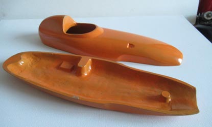
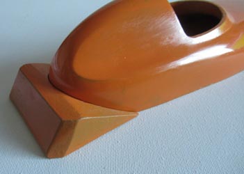
The pattern was carved from balsa wood as it is easy to carve and modify if need be, due allowance being made for the shrinkage when casting aluminium. Two castings were made one to be used as the future production pattern and one as a prototype car. A balsa wood pattern will only last a few castings however, especially if modern epoxy quick setting sands are used, which is normal today. The pattern gets damaged trying to prise it from the now very hard, almost brick like, sand mould.
 |
 |
 |
| Super level of detailing lifts this model | ||
Ian Harper had made a hand beaten car of his own design about two years ago and updated it last year with rear springing using a Titanium strip for the rear spring, an idea used in the early days of tether car modelling unbeknown to Ian, great minds think alike? I liked the idea and decided I would use it on the BRM build and Ian offered me a piece of his Titanium strip for my car. The advantages are ease of installation with simplicity and less space required for the springing, it does not leak oil like the spring dampers often do. I made the spring fixed near its centre to the chassis with the twin shaft Redfin engine mounted at the rear and front suspension at the front end. I waisted it at the forward end to reduce the stiffness in the light of trials. The spring does need damping and again Ian pioneered the use of drone rotor blade dampers which I also liked as rubber is self damping. They fix to small buttons welded inside the body top above the spring ends. You can fit the smaller size available inside the larger ones to gain more damping if needed.
 |
 |
 |
| Suspension dampers | 'Curly Carb & NVA | Internal layout |
My model would be based on the P25 British Racing Partnership car driven by that man again, Stirling Moss, and finished in the light British Racing green. A colour I first became aware of when reading about its use on the DH 88 Comet Racer aeroplane built for the England/Australia Air Race in 1934, when I was still in short trousers? My wife says at 87 I still am, ho ho!! It makes a nice change from the dark green colour. I believe it was also used on some British racing cars in the vintage period and which ran at Brooklands.
 |
 |
 |
| Racing mirrors | 'Curly carb' | Wrap round windscreen |
|
I like to add scale detail to my models and add as much realism as practically possible. I try to avoid cut outs in the body to accommodate intakes, exhausts and NVA’s etc. So I added a scale exhaust made in copper and silver soldered to join and fix it to a mounting plate fixed to the lower body or chassis with 8BA studs. A cut out had to be made to gain the appearance of it coming from within the body. The carburettor air intake was added, along with a dummy radiator grill and tie rods to avoid body flex in the nose. The rear view mirrors employed a raised rear edge which I over emphasised, otherwise it would be virtually invisible at this scale size. A clear soft plastic windscreen was fixed with clear ultra violet fixing adhesive after painting in stove enamel which gives a durable, good, fuel proof finish. Right: Exquisite exhaust manifold |
|
The fuel tank is made from brass sheet soldered together with a vented screwed filler cap and a single feed pipe to the Oliver pattern fuel cut off. The tank sits astride the spring to give clearance for movement and is in the centre of the body in line with the NVA jet in a 'curly carburettor'. This avoids a cut out through the rear body for the standard straight intakes of both Redfin and Oliver twin shaft engines. It helps keep dirt out of the intake as well. The 'curly carb' is made from Tungem tubing used in the marine industry, it usually has a thicker wall thickness which helps avoid kinking when bending tightly and it also silver solders nicely to fix the brass nipple which screws into the engine intake port.
I hope to run the car at the SAM 35 first meeting of 2026 over 11th and 12th of April and most likely at other events later in the year as well. Please come and join us you will be made very welcome, even if spectating.
The Oliver model car body castings are available from Ian Harper at:-ianharper1961(at)gmail.com©copyrightOTW/JohnGoodall2026