|
Home Updates Hydros Cars Engines Contacts Links 1066 History 1066 Engines Contact On The Wire |
Ten Sixty Six Products: Cars and Kits
|
MRC (Model Racing Car) |
|
The arrival of the first car from the company, called simply the 1066 Model Racing Car, was somewhat organic, as the parts came on to the market bit by bit, with the chassis being the last item offered. A body was added even later. Every single component for the car was given a code to identify it. Many of the early tethered car designs and plans also specified the use of 1066 components.
|
|
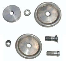
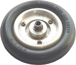
Wheels were the first items to appear and comprised two pressed aluminium discs held apart by an aluminium spacer. The discs were assembled on a hub, which had either a knockoff type spinner or a tommy bar hole on the outer end, and was threaded ¼ BSF internally with a left or right hand thread. (Many have been damaged through this when brute force has been used to screw the axles in). A fine rate thread on the outside of the hub enabled the unit to be clamped with a thin aluminium nut. A turned aluminium brake drum would also screw onto this hub. The spinner style hubs were discontinued after a short while, leaving just the tommy bar versions. |
|
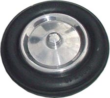
Tyres were originally solid ‘Hastings Racing Cord’, later named ‘1066 Solid Racing Cord’ but eventually precision ‘air-cored’ tyres were made available which made for weight reduction and a smoother ride. The air-cored tyres were similar to a modern tubeless tyre and only retained the air through the clamping pressure on the beads. Stopping the tyres turning in the discs was a problem with driving wheels, although it was claimed that they would never strip from the wheels. A complete wheel and tyre would cost you a princely 15/6 (77p) A larger size of tyre and wheel did become available but still with the same 6.0 x 16 on the tyre wall. These are relatively rare and were often in a grey rubber but so far no hubs for these have been identified. |
|
|
|
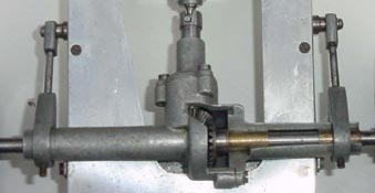
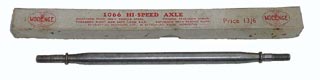
Next to turn up was an axle unit. Three castings made up the axle, which was the full width of the car. A 3/16" input shaft mated to the pinion of a set of 2:1 bevel gears and the crown wheel was pinned to a ¼" axle. All shafts ran in bronze bearing sleeves. Axles were threaded left and right hand to match the wheel hubs. Casting sets cost 10/6 (52p) with the gears, axles and bushes having to be purchased separately. In Model cars in 1947, Lawrence Sparey described how to machine up one of these axles. Left: Sectioned front axle |
|
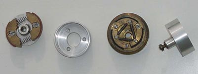
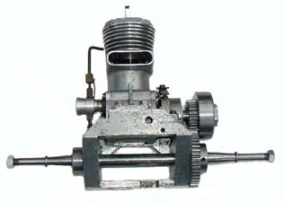
The last element of the drive train was a clutch. 1066 offered two quite distinct units, both of which required the same standard flywheel. CL1 was a standard three shoed
centrifugal type, with the shoes screwed directly onto the face of the flywheel.
An aluminium drum ran on the extended end of a long collett that replaced the
short version used with a prop driver. A 1/4" dia ball joint
took the drive directly to the axle unit. |
|
CL2 was a separate unit which mated to the flywheel via the three screw holes used for the shoes on CL1. This clutch had two shoes which were spring loaded so that they were permanently engaged and claimed to provide a ‘soft take up’. Output arrangements were the same as for the three shoe version.
If the published plan for the car is followed, the engine will only fit if the CL2 clutch is used. The holes for the motor mount must be drilled further back if the CL1 unit is to be used. This then limits the space for the fuel tank as well. If this were not problem enough, the engine mount provided has a cut out that is far too large for any of the 1066 motors and is also shown too large on the plan. Another error is with the supplied tank brackets that are punched correctly for the mounting holes fore and aft but cut too short to fit the chassis. As an aside, if a standard 3/8" plug is fitted into the motor it fouls the body. Yet more examples of 1066 ‘design glitches’?
|
|
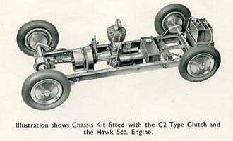
Finally a complete chassis kit was marketed. This was available in three stages of completion. K1 at 62/6 (£3.12), consisted components and materials, but with all the machining to do. K2 had a clutch added to the basic package and cost 92/6 (£4.62) and K3, which was a complete car ready to assemble at £6-12-6 (£6.52). Folded aluminium side rails 5/8x1/4 were held together by a cast front member and a folded rear member. The engine plate and steering unit gave some rigidity to the whole assembly. Axles were located by radius rods screwed into cast teardrop axle mounts with suspension by coil springs and spring pins through very flimsy steel angles. The back axle rotated along with the wheels, in two bronze bushes that were held into 2 die-cast ‘axle mounts’ by setscrews. |
|
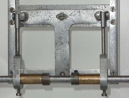
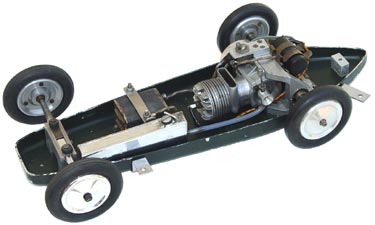
The front radius rods were straight and bolted to the side members. The full width axle housing clamped into the cast radius rod ends with 2 more setscrews. The rear rods however had to be cranked quite sharply to attach to the steering mechanism. A later modification involved running the rear spring pins directly through the chassis member. This allowed the radius rods to be kept straight, but left large unsupported overhangs for the axle as the mounts and bearings were moved inboard by 1" each side. Plans had a sticker attached showing these modifications. Right: Straight radius rods and rudimentary steering mechanism |
|
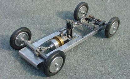
All illustrations in the 1066 catalogues were artist's impressions of what the company intended to produce but did not match what was eventually manufactured. The car as shown below was supposedly finished off with a large rectangular fuel tank between the chassis members and two NIFE cells in a battery holder attached to the rear of the chassis yet neither an original fuel tank or battery box has yet come to light. The artist has taken certain liberties along the way in several instances.
 |
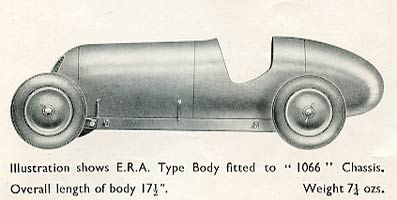 |
| Original illustrations show a great deal of artistic ability and understanding of the product even before it existed | |
|
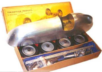
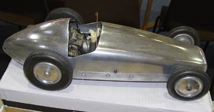
Original adverts and the catalogues show what is referred to as an ‘ERA type body’ but this bears little resemblance to what was eventually produced and certainly not like an ERA. The production body was a simple pressing from 20 SWG aluminium that has a more ‘twenties’ look. The body was available in three states. Unfinished for 24/6 (£1.42). Buffed and polished at 29/6 (£1.47). The most expensive option was to have it coloured and anodised for a total of 38/6 (£1.92). In 1949 a ‘Luxury Kit’ was advertised, which included a buffed and polished body, a large front valance, a radiator grill, and upholstery for the cockpit. A sectioned version of this luxury kit seen here was discovered in the collection of the late Gerry Buck. |
|
|
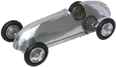
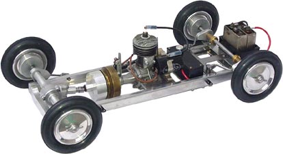
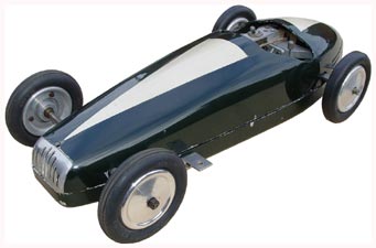
The CH1 chassis was very flimsy and really only suitable for motors up to 5cc. Chassis kits were advertised for 2.5, 5 and 10cc cars, but as far as we are aware, there was never a 2.5cc car that existed as a separate entity. The MRC shown right is a modern build using original components and is as close to the illustration as possible. As can be seen, there is no room for the extended drive shaft. The Hawk motor has the serial number of CHG 1000, the very first produced commercially and obtained personally from Mr Hastings by the previous owner. |
|
|
Conquest |
 |
|
Instead of a chassis, 2 large pressings in 14swg aluminium made a pan and body that butted together. A cast motor mount carried a turned axle in two ball races. The 3/8" hardened and tempered axles were tapered, flanged and threaded ¼ BSF left and right hand. Provision was made on the motor mount for adding a magneto behind the axle, driven by a second spur gear. The motor mount and axle at £1-10 (£1.50) and 13/6 (67p) respectively, were offered as separate items for those who wished to ‘do their own thing’. |
|
|
|
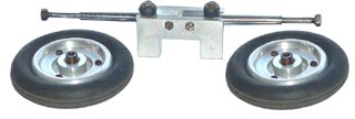
The front axle unit was bolted directly to the pan and had two swing axles with rubber bush springing mounted into an aluminium casting. Two tether brackets made from bent steel strip were bolted through the pan, one behind the motor mount and one behind the front wheels. Like most other spur drive, rear rotary valve installations, it was difficult to get the fuel tank and outlet mounted anywhere near the desired location. |
|
|
|
The wheels and tyres supplied for the 5cc MRC car were obviously not up to the task for a 10cc car so completely new heavy-duty wheels and tyres were provided. The new wheels were made from two turned castings. The outer casting carried the hub and half the rim, while the inner ring clamped the tyre to this outer disc via 3 countersunk screws. The hub had a taper bore fitted either with a collet, which could be pinned to the driving axle when the wheel nut was tightened or a solid phosphor bronze bush for the front wheels. Tyres were available in 3 ½" or 4" dia, but strangely no wheels for the 4" tyres have yet been found. A pair of wheels and tyres was priced at £1-15-0 (£1.75) |
|
|
|
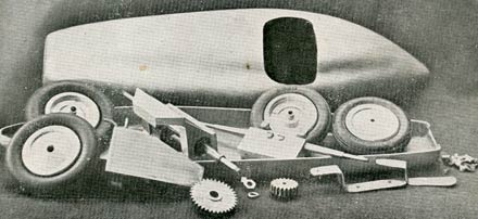
As with the MRC, the Conquest kit was supplied neatly boxed with all the mechanical parts required for the car. The body pressings were boxed separately. The cost of the kit was £10-10-0 (£10.50). The original illustration of the kit shows a very plain mock up of the top half, rather than the eventual fluted pressing. A variation of the top body pressing with a much higher headrest was seen but this is believed to be a prototype, which came from the Prescott family. The car is fitted with MRC wheels and tyres rather than the correct heavy duty ones. |
|
|
|
| Early body with higher headrest | Jack Hadlow's factory car with experimental Conqueror motor |
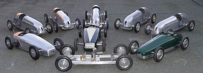
Large quantities of 1066 spares and components have continued to appear on the market with the MRC being one of the more common cars to appear for sale, allowing enthusiasts to build a significant number of new cars from original parts.
Thanks Peter Hill, John Goodall and Brian Walter for items and images
©copyrightOTW2021