

|
Home Updates Hydros Cars Engines Contacts Links ←Previous Next→ Contact On The Wire |
Aries, Under the skin of an aircar
John Goodall
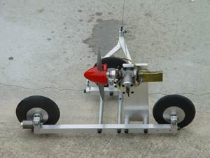
Shortly after tethered cars began to be run regularly again a few year ago, the inevitable pursuit of speed began. Firstly, more traditional cars that were upgraded with more powerful motors and then more radical designs that were more engineering exercises than model building. The late Dick Roberts started the trend with the first of his 'proa' cars, originally with a CS Oliver and then a full on Oliver motor. With regular development and modification it gradually increased the Gt Carlton track record to close on 80mph. Martin Coe utilised a very basic chassis but with an immensely powerful K12 motor to break 80mph for the first time, instigating a full on power and design race. The only real limitations are a ban on any tuned, power or mini pipes and the necessity to be able to launch and keep the car on the track.
 |
 |
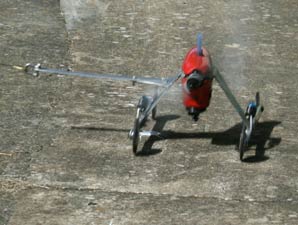 |
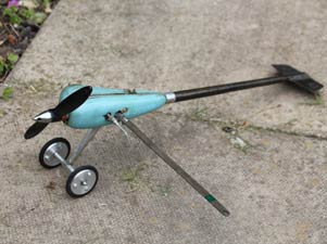
| Dick's 'proa' in its original form | Eastern 'pod and boom aircar' KMD motor | Latvian KMD powered aircar |
|
|
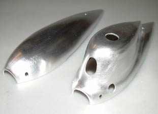
The eastern Europeans have been running aircars for many years and do use tuned pipes so it was not long before a couple of typical 'pod and boom' cars were imported that proved almost impossible to launch and a four wheeled Latvian device that reeled of lap after lap at close on 85mph, the race was joined. KMD team race motors, Rothwells, Parras, very special Olivers and more. Many variations on designs are now being explored and in 2021, the first running of the Dick Roberts Aircar Trophy saw John Goodall winning with his Aries II. Left: John with trophy and final version of Dick's 'proa' John has kindly sent us an extended article detailing the development of the Aries series and in particular the latest manifestation, Aries III, a 1.5cc version. What each of the cars share is an exquisitely crafted speed cowl, beaten up by hand from aluminium sheet. |
|
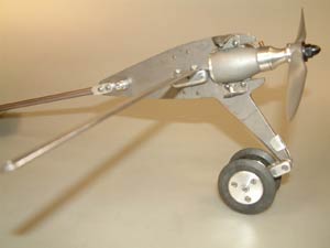
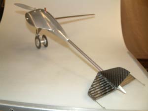
Aries I: The first British version of an eastern European 'pod and boom' flying tail aircar. (right:) The car works on the principle that as soon as it is launched the combination of the vestigial tail and thrust line has the car running on the two front wheels that are sprung. Having built and attempted to run the car John made a number of alterations that are detailed below. Changes made to Aires 1. I made a new crutch in 0.100" titanium increased from the original 2mm. This introduced a few problems in body half fit, but mainly in cutting the shape out with hacksaw blades, getting through three, and this after blunting my last band saw blade?? It is the most difficult grade to work I have used. The body fairing fixings each had to be altered to account for the different crutch thickness. The tail boom fixing slot had to be adjusted as well. Turning the suspension leg round meant adjusting the piano wire spring and fitting a new anchor, the rest being a simple reversal. |
|
To get balance after turning the suspension rearwards with the existing tether arm slot position in the body fairing, meant moving the engine and fuel tank rearwards by 3.5mm too. The only thing I have not done is make an exhaust collector although I did increase the outlet hole to allow for extra gas passing. I will see how and if it performs, before making this latter change?
 |
 |
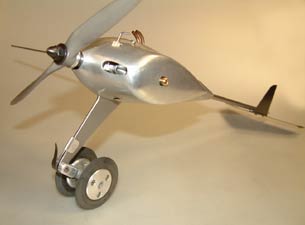 |
| New crutch and front axle | Carbon fibre flying tail and stabilising fin | Reversed front suspension |
Aires II:
 |
 |
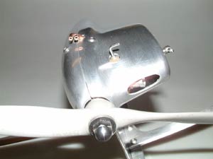 |
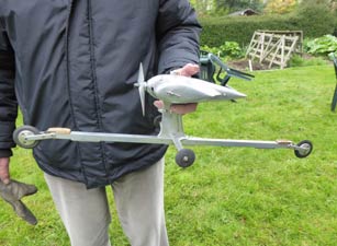
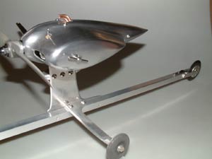
| Aries II set up for clockwise running | Stabiliser | Exquisite aluminium speed cowl |
The engine I now have in both Aires 1 and 2 is the K12. This was made by Technohobby in Ukraine and is a direct copy of an Oliver. Alan Knight was involved in sorting out some of the gremlins and the result is a powerful engine that seems relatively easy to start and even stop by finger power?? I saw Martin Coe using his at Peter's track about a year or so ago to break the track record and asked Martin about it and ended up buying the first one off Ed Needham and then a second after the Schneurle ported CS Oliver I initially used in Aires 1developed starting problems and needed a rebore to cure it. Taffy Bollen offered his help with this and recognised the schneurle ported engine as one he had built. This surprised me greatly as I bought it off an Australian at the Nationals, must be ten or twelve years ago, and I thought the Australian had built it??
Aires III:
In the quest for a tether vehicle to run at Peter Hill’s track up in Great Carlton near Louth, where I had little success with conventional tether cars. I decided to build an airscrew driven vehicle very much along the lines of my successful Aires 2. I needed something more sedate and a little lighter than Aires 2, so in keeping with my preferred Oliver engines usage, opted for Oliver Cub power and searched around for a suitable motor. Alan Knight mentioned he had an Oliver Cub with Schneurle porting and an ABC cylinder assembly, which made 22,000 revs on test with a six inch prop and this intrigued me and Alan kindly let me purchase it.
I talked to Peter Hill on his track surface condition and Peter mentioned the best direction of rotation to negotiate the track irregularities, so anti clockwise looking from above was duly chosen, which is in opposite direction to my previous aircars chosen for engine torque to improve line tension.
 |
 |
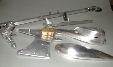
| The sum of parts to build Aries III | Sculpted aluminium pylon |
|
I decided as an experiment to make a slightly more radical vehicle again basically a two wheeler when at speed, with a third outrigger wheel for stability when static and at start and end or runs. This wheel lifts clear of the track surface as speed increases to reduce wheel drag. The device, you could call it a motorcycle but not a car, is canted inwards at speed to give a rotational tendency, leaning inwards motorcycle like. I am a motorcyclist after all, which I still enjoy greatly. The main wheels would need a larger diameter to improve bump negotiation. The suspension is very similar to Aires 2 with abrasive disc cut leaf springs controlling the milled alloy arms. The outrigger was attached to the tether arm to reduce drag and complexity with a clamp device and the piano wire wheel leg Locktited into the clamp device. |
|
Construction followed the form of my previous aircars with an alloy crutch screwed to a long alloy beam made about 2 inches shorter than Aires 2 to give longitudinal stability. The motor was mounted on this, along with a fuel tank and means of later securing the enveloping body cum cowling which I intended to hand beat as before. This would be slightly smaller in line with the motor dimensions. The forward fixing was effected by making a conical alloy ring to fit round the front bearing housing on the motor with four tapped holes for securing the body front end. I milled four slots around the periphery to admit cooling air round the front bearing area and to reduce drag behind the prop. At the rear I used a pair of pillars tapped straight through and placed one each side with a joining stud and Locktited for security. The tether arm is made from stainless steel and attached to an alloy bracket screwed to the crutch at an angle consistent with the inward lean angle. The fixing position determined by vertical and lateral balance points.
|
I first ran the device without the bodywork which was not then made at Peter’s track and it seemed pretty quick even with an oversize 7 x 6 propeller, Alan had advised a 6 inch prop. Fingers?? Truth is I cannot find any suitable 6 inch diameter props, help needed here please? I had two runs and it ran with great stability in the mid 60mph range, which was pleasing, and the motor went very well too. |
|
|
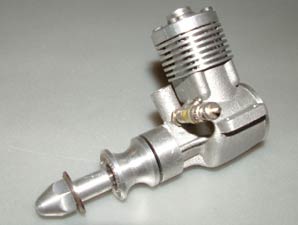
| Aires III on its Gt Carlton debut | Oliver inspired 1.5cc motor |
I ran the device again the next day at Buckminster and again it was fairly quick, recording 70 mph which I did not think was too shoddy for an over propped 1.5c motor, especially with the track surface problems. It will be interesting to see what it will achieve now the bodywork has been made and fitted and hopefully with a more appropriate prop size?
 |
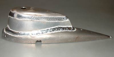 |
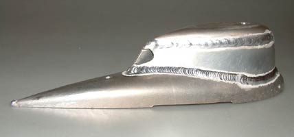
| Superb welding on the top half of the cowl | |
 |
 |
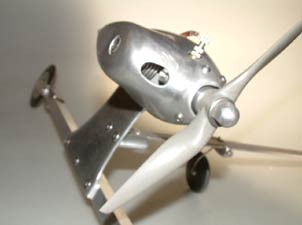 |
| Cowl fettled | Oliver based 1.5ccmotor | Aries III complete |
I have incorporated some of these ideas into Aires 2 since I ran Aires 3 and hope this earlier device will now top 90mph, after making 88 mph in the Dick Roberts Trophy event.
 |
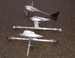 |
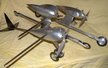
| From Front: Aries I, II, III | From Top: Aries 1, II, III |
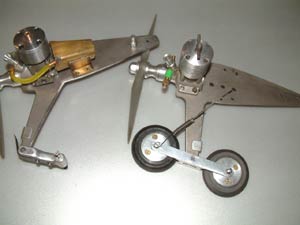
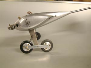
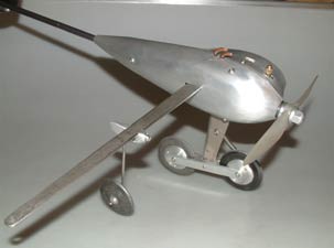
More recently I have been modifying Aires 1 to what I think will be an improved wheel arrangement for launch reliability after realising the original set up was very unstable and relied on horsing skills we do not yet have in the UK to effect a launch. A launch is possible as shown by Martin Coe who now owns the KMD powered device I obtained off Pavel Pirov from Latvia and which inspired my Aires 1 design. I have now changed the wheel layout from side by side to a tandem bicycle arrangement, which I believe and hope will greatly facilitate and improve launch reliability and also directional stability. My theory is that with the main support wheel behind the CG, directional stability will be positive, whereas with it in front of the CG it is very unstable, as demonstrated in full size tricycle undercarriage aircraft designs.
My idea is that the front wheel will be set higher than the main one, so that statically the nose will be lower than the tail at launch and hopefully also at the end of the run? The tail aerodynamic force will cause the nose wheel to rise clear of the ground and it should run only on the main wheel once up to speed. So it will effectively be a mono wheel in practise, something I have often theorised about since my teenage control line flying days. I am using the original titanium crutch to mount the milled alloy suspension beam, with a wheel at each end of it and pivoted at its centre. A tension spring will provide the suspension action. An outrigger wheel is now mounted on the tether arm for static stability. The stance may look odd, but if it works I am not too bothered.
 |
 |
 |
|
The first picture shows the second
version with K12 motor and third version made with Taff Bollen
Special motor. |
||
I had made an interim modification to Aires 1 with the wheel swinging arm reversed such that the wheels were just in front of the CG for better directional stability and when Pavel saw the pictures I sent him, commented he did not think it would work and to change it back, hence my most recent alterations. He also mentioned they use very young horser’s in Latvia who are quick to respond to the swings seen at launch in the unstable forward wheel designs with a very positive pull and highly held position of the tether wire. He sent me some video links of them in action and a few stills. My conclusion was there had to be a better and more reliable way forward for us here, at our skill levels. Topically, the proof of the pudding is in the eating??
RC cut off for Aircars Fitted to Aries 2
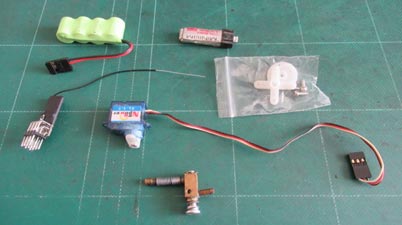
It was decided during the 2024 season that the vastly increased speeds aircars were achieving required something more sophisticated in the way of stopping them than the 'smother blanket' used when speed seldom exceeded 35mph. Roger Gedge has been using a RC fuel cut-off system for a while, which is very effective. He described this in a previous video post, but now, John Goodall has very kindly produced this illustrated guide to how he has fitted this system to his Aries 2 aircar. The system could be equally well suited to any aircar.
I am indebted to Roger Gedge for giving me
the system shown here and installed in the latest version of my Aires 2 now
designated Aires 2-2. It incorporates a larger nose on the body to
facilitate fitting a 1 1/2inch spinner so that I can use an electric
starter, as hand flicking has become hazardous for me and the only way I can
safely continue to run them.
 |
.jpg) |
|
Shows the basic kit TR cut off not used |
Details of supplier |
Roger advised using a rotary fuel cut off
to reduce torque on the diminutive servo and so this was the first thing I
made after the new body shells were finished and fitted. I made this out of
brass bar milling the body into a basic “L” shape which would be soft solder
mounted to the fuel tank bottom edge as space is very limited within the
cowling. The main body was drilled and reamed with a 5/32 inch hole into
which would locate the pivoting spindle and in turn through which was
drilled a 2mm hole for the fuel passage. The spindle was spring loaded at
it’s upper end to give controlled friction and yet is still free to move. I
planned to run the feed pipe from the outer most corner of the tank to the
cut off from the bottom of the tank, but had to abandon this after the pipe
contacted the body inside with a trial fit. I then rerouted it through the
side of the tank and again into the outer corner. The two copper pipes into
the cut off body were silver soldered to avoid them moving when soft
soldering the body to the tank. The outlet pipe angle and position was
critical to fit in and obtain a good kink free fuel pipe run, clear of the
body.
.jpg) |
.jpg) |
.jpg) |
| Rotary cut off soldered to tank bottom | Operating arm of cut off | Limited space for fitting the rotary valve |
The servo was mounted in an oblong cut-out drilled and filed to suit in the crutch. I did later widen this out to move the operating arm clear of the body inside, after further fouling. I secured the servo in place with clear silicon sealant which gives some slight resilience and this also sealed the exhaust side and help’s to keep exhaust oil from the outer side where the radio receiver would be fitted and most of the electrics with a suitable switch, the switch knob is accessible through a slot filed in the outer body. I mounted the diminutive receiver using self adhesive servo Velcro tape kindly given me by friend Ian Harper, like Roger another recent convert to tether cars and a good welder too, Ian welded the new Aires body for me, so judge for yourself.
.jpg) |
.jpg) |
.jpg) |
| The basic installation with transmitter | Close view of installation RC at top | The basic installation with transmitter |
The battery was mounted in a sponge lined
U shape alloy holder screwed to the crutch so the battery could be changed
easily when expended. It is held in place by centrifugal force when running.
The switch was mounted on an alloy bracket at a slight angle to match the
body side as close as possible with a plug and socket to allow the battery
change and for charging same. An insulating foam was placed between engine
rear and battery to reduce heat transfer. The system works well on test and
remains to be tried in use now. Roger's is well proven in numerous track
outings.
.jpg) |
.jpg) |
.jpg) |
|
New body allows spinner and improved choke accessibility |
Switch on underside of body |
|
©copyrightJohnGoodall/OTW2024