|
Home Updates Hydros Cars Engines Contacts Links ←Previous Next→ Aircar Article Contact On The Wire |
|
|
Steve Betney's Work Bench |
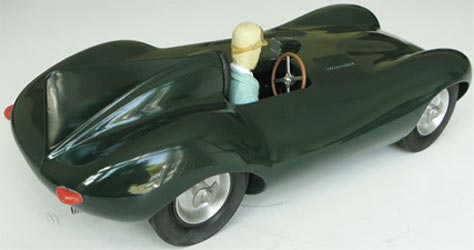
1/10th SCALE JAGUAR D TYPE MODEL
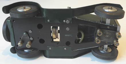
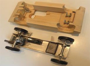
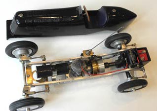
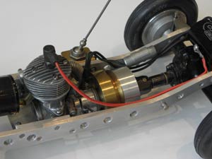
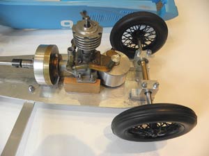
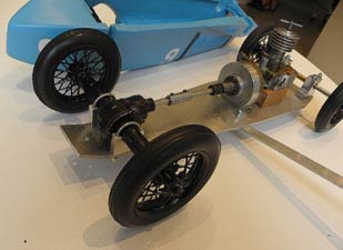
Some 7 years or so ago a small number of MVVS tethered car moving chassis assemblies in "New Old Stock" condition became available via eBay from the Czech Republic. It is believed that up to 100 of these were made by MVVS in the late 1950s or 60s, and they were powered by an MVVS Junior 2cc front rotary diesel engine with a fixed 2nd shaft replacing the back-plate, intended for a Mercedes Benz W196 Silver Arrow carved wooden model body. The original chassis drawing by Jaroslav Broz shows a Bus 2.5cc f/r diesel for power, though I don’t think that this was ever produced in any quantity. I bought one of these because it looked well and solidly made, and in the hope that I could use it as the basis for a Jaguar XK 120, 150 or D Type model.
|
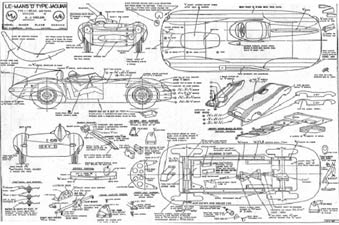
Working from scale drawings of these types, the wheelbase, track and tyre diameter were a close enough fit for a 1/10th scale D Type, and good old Peter Hill of Retro Racing Club fame provided a print of the 1/8th scale Model Maker plan no. MM 367 for this, which I reduced to 1/10th scale by photocopying it in sections at 0.8x magnification. At this stage it was thought that this might be quite a quick project, and being reasonably pleased with the build quality of the chassis I had, a second one was procured when the chance came up, with the intention of making 2 models. |
|
However, hard experience shows that making 2 identical models on a project like this takes just about exactly twice the time it takes to make one, the only time really saved is in the research, planning and parts procurement stages. However, please see later, as this might just provide someone with an opportunity to get a quick and relatively easy way to get such a model!
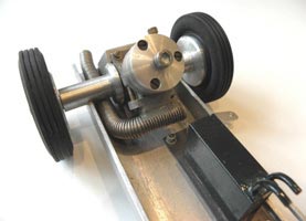
The MVVS tyres fitted were rather plain, non-scale types which were just beginning to craze with age, and it was found that replica Movo Pirelli 70mm diameter ones would fit nicely and vastly improve scale appearance, so I managed to procure some sets of these from Hungary with Stu Robinson’s help. The cast Movo/Pirelli lettering was carefully shaved off with a sharp scalpel & they were then sanded to a nice matt finish in the lathe & they look great, but with no "Dunlop" lettering as would be ideal. The original screws used by MVVS on the chassis were rather average quality, so all of these were upgraded and nyloc nuts fitted. I didn’t feel that the front lead balance weight and tether line attachment bracket were appropriately secure, being retained by the original M3 screws threaded into the balance weight (yes, a thread cut into lead….), so I put longer screws right through, secured by nyloc nuts. A KeilKraft 15cc team race fuel tank was modified and fitted using a brass mounting plate.|
|
|
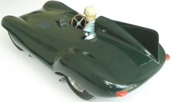
I eventually managed to get hold of a couple of MVVS Junior silencers, and these were cut down to just the manifold stub secured to the engine’s exhaust by 2 screws & glued with metal epoxy into a reticulated, bendy stainless steel 8mm i.d. pipe with a blanking plug formed to serve as a rather neat, rear exhaust exit arrangement (see image). |
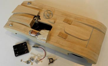
To make the bodies, I had some top grade obechi wood custom sawn and sanded to 10mm final thickness, and made up 2 sets of parts for the laminated body construction. The central body section is made up from 6 obechi slices and the sides from 3 slices each, all band-sawn to individual shape. The centre section I chose to secure to the chassis with 3 spring tool clips, one fixing round each of the front axle ball bearing housings and a single rear one gripping the dummy shaft on the engine.
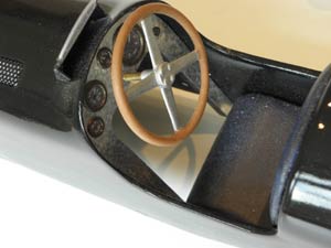
It’s a lot of fun carving the under-body to fit the front and rear chassis ends and particularly around the Junior engine’s cylinder and fuel needle valve areas. Some special metric cap screws were needed to replace the original T bar compression screws, which would have spoiled the appearance of the cockpit top and driver’s shoulder area. One set of the top and side laminated parts were then glued up to make a whole body blank, then the job of shaping by carving and sanding the inside and outside to shape undertaken – LOTS of careful work here, particularly the rather thin sectioned wheel arches. When completed and finish sanded, the cam-box cover bump on the bonnet and the nice rear fin and its fairing pieces can be added and finished to shape. This is followed by a few coats of cellulose sanding sealer carefully rubbed down between coats and then I chose to use a tissue and dope covering to give a harder skin to the obechi surface. I just love louvers on a model, so some laminated blocks of shaped louver were made up from strips of 1.5 & 1.0mm shaped basswood sections which were then carefully set into shallow rectangular recesses cut into the finished top of the body. The final external body details to be added were the driver’s rear view mirror, an obechi carving with a mirrored plastic facing, and a pair of rear lights sawn to shape and filed up from some small pieces of 5mm thick aluminium sheet, polished and attached with screwed pins.
 |
 |
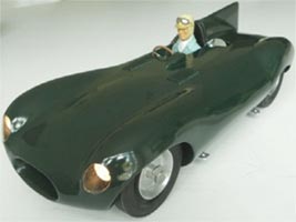 |
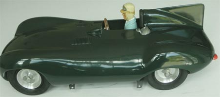
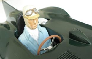
The driver figure used is one of Dave Banks’ beautifully sculpted 1/10th scale British 1950s types, made by Dave especially for this particular model (and suitable for all other 1/10th scale types of course). This was fitted with small neodymium magnets embedded with epoxy glue into the sides of the upper arms & the cockpit sides. The steering wheel is an American repro O&R casting, which was the only decent quality item that could be found of the correct size, though it should really be a 3 spoke type.
Now that the body was completely shaped and ready for final cellulose finishing, I had the bright (groan…..) idea to fit working headlights, as I wanted to fit clear acetate headlamp covers anyway. A pair of 15mm diameter, metallised plastic model boat searchlight bodies were found to be suitable, fitted with 6v grain of wheat bulbs (though I now wish that I had used small LEDs for longevity & cool working). The recessed housings for these were carefully gouged out in the front wheel arches, after moulding the acetate around the headlamp position areas by draping over-sized pieces of thick sheet over them softened with a heat gun and using cotton gloves to hold them in position until cooled and re-hardened, then finally cutting these to oval outlines and cementing into position.
|
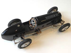
The wires from the bulbs exit through holes into the front wheel arches and are connected to a strategically placed toggle switch placed near the driver’s side front wheel arch in an accessible position. The power source is a 4xAAA battery pack in a plastic holder mounted with screws on the underside of the bonnet, so all parts are together in the removable body shell. After masking off the now installed headlamp covers and rear light fittings, a few coats of grey cellulose primer were sprayed on and rubbed down, then many, many coats of Jaguar British Racing Green cellulose paint sprayed and rubbed down between coats, this stage taking place on and off over a period of years! Why years? |
|
Basically because I have far too many bloody projects on the go at any given time across my various interests, and I move around between them as my mood and motivation take me, though this might be my excuse for lack of application and concentration.
 |
 |
The model as pictured here is still probably not in its final form, as I haven’t yet decided whether to turn up a new set of alloy hubs each with 15 drilled holes to simulate the lightweight pressed aluminium rims used on the Le Mans D Type cars. My contact Chris Garcia in California is making me up some scale 54 wire spoke wheels as fitted to the original works development D Type, then I can see if these look better, otherwise they can be used on a Mercedes W196 body for yet another one of these MVVS chassis I have. We’ll just have to see. I have also moulded a wrap-around windscreen for the Jags, but have struggled with finding a really neat and scale way to attach this without marring the body top. When these weighty deliberations are finalised I shall add appropriate final body finish details like racing numbers and road number plates to my model then gloss fuel proof it all, but until then I will continue to love it in its plain BRG livery, as it sits alongside the much smaller scale repro Vega D Type Jag on my shelf.
 |
 |
Railcar Renovation
A rail car that I have recently finished renovating might just possibly be of some interest? It is a rather toy-like, MG-ish appearance car, which is probably from the very early 1950s and has a lot of charm, to my eye at least.
It was mis-listed and mis-described on eBay a while ago by a steam toy dealer and I paid far too much for it, but now think that it was just about worth it in the end. The engine is a nearly new Mills 0.75cc Mk I. The car came with 2.0" diameter Triang tyre wheels fitted, so that it rocked on its zonkers, as it should have had 2 ½" diameter wheels. Described as having been Mills 1.3cc Mk 2 powered and run many times, despite the 60 odd years worth of oil, dust and grime, I suspect that it had done only light duty as it cleaned up very well. It still has the original engineer’s blue marking-out fluid on the inside of the very accurately folded aluminium body parts. It was obviously made by a very skilled model engineer, but he didn't know much about operating engines in car models. The nice rectangular fuel tank is at the rear of the car held in place by the spare wheel with a mounting bolt through it, and this makes it a full 6" behind the engine, feeding it via a 1/8" o.d. brass pipe against the direction of travel. That's why its original 2 ½" wheels disappeared to be used on another project in all probability, the car to be later fitted with the under-sized Triang jobs by some yoyo or other to try to make it look complete and original and worth a few bob.
 |
 |
 |
It has the very Wreford-like clutch and rear axle/bevel gear box. I'm fairly convinced after re-inspecting these carefully in the light of your and Peter's opinion and comparing them with name-stamped originals that the clutch is not a skilfully made copy but an early, unstamped Wreford item, whilst the bevel gearbox may be an extremely well-made copy but just possibly even a very early, original Wreford version too; maybe we'll never find out.
|
The car was unpainted, another feature leading to light use only, fuel feed function suspicions, so I gave it some cellulose primer and green cellulose finish so that it didn't look so naked. Fitted a set of Bill Bannister's RRC Raylite type 2½" tyres with ball races to the front, to lift the zonkers off the deck. Zonkers to the unitiated is the term used for the rail guides seen here front and rear. There was a great deal of aggravation ending in a court case over certain versions of these, but that is a different story. OTW |
|
Latest from Steve, a Pratley ERA
In the Model Car Manual published in 1949 Geoffrey Deason described the building of a Semi-Scale version of Raymond Mays' D type ERA. The original design was one of a series by Harold Pratley to take advantage of common commercial components that were available at that time. Helpfully, pre-formed aluminium chassis rails were available from Ken Whiston's famous surplus emporium at the princely sum of five bob (25p). The suspension specified on the drawings was a bit of a dog's dinner with leading radius arms front and rear locating axles sprung with coil springs, although there was the option of using leaf springs at the rear. Wheels and tyres were 1066, gearbox either Electra or 1066 (or whatever was available) and similarly with the clutch. The motor in the original was a Canadian Super Hurricane, hardly one of the most freely available options.
 |
 |
 |
Steve's replica follows the original faithfully, but uses one of the other specified alternative options by making the chassis rails from solid 3/16th Dural. Deason points out in his article that decisions on the various alternatives must be made 'before proceeding with the chassis'. The use of contemporary components and motor has enhanced the build of this replica considerably.
 |
 |
 |
The bodywork, as we have come to expect from Steve's builds, is a work of art. The original used a basic balsa 'box' with shaping added via planking and scoring to allow the tail to be bent. Steve has adopted a much more sound modelling process for his, and hopefully he will tell us how this was achieved. We have heard by word of mouth the amount of work on this aspect alone. The only question remaining is whether Steve managed to add all 136 louvres to his model?
Thanks to Steve for these photos and another superb example of his modelling skills.
Update Sept 2015: Well, yes he did, as he explains below
The ERA's
body is bandsawn from a single, very hard block of solid balsa, carved,
hollowed and sanded to final shape then sanding sealer/tissue, dope
skinned. Louvres (yes, all 136 of them) are made in laminated blocks of
basswood strips, set into shallow rectangular recesses cut into the
body's surface. Finish was then several coats of grey cellulose primer,
rubbed down between applications, then 10-12 coats of black cellulose
sprayed on with much rubbing down as I kept getting wrinkles where the
latest coat cut into the original paint. Got there in the end though.
Cockpit instruments are the usual model brass portholes, chemically
browned and with scale model aero/boat dials I had originally intended to finish this model in
Prince Birabongse's livery but decided on the Raymond Mays' version in
the end because of the irresistible lightening holes drilled in the
chassis frame rails.
Smallest
Mills 1.3cc powered Tethered Car Ever?
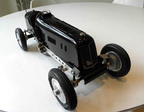
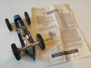
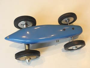
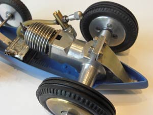
Some 6 years ago at Gilding’s annual model engine auction my attention was attracted to a lot described as a Mills 1.3cc diesel modified for model car use. On inspection, it proved to be an unused Mills 1.3cc Mk II Series I engine with a polished aluminium crankcase, not the usual black finished magnesium. It had a well made 2nd, non-driven shaft in place of the backplate and a neat, right-angled venturi attachment instead of the normal, extended-trumpet type with tank assembly. A pair of totally perished Frog aero wheels of 2 1/4" diameter were fitted, and it was ingeniously mounted in a tiny, skilfully hand beaten car bottom pan of ultra lightweight construction just 7" long. I was lucky and made the winning bid, there being only one other bidder, the auction population comprising almost all aeromodellers interested only in engines for flying, so I got it not too expensively.
Research revealed that the engine, which bears the serial number 43 09, is a very rare Mills indeed. The advertisement in the June 1948 Aeromodeller magazine announcing the "new Mills Diesel Mk II" was illustrated with a picture of this polished aluminium style engine, described as "polished all over and the steel parts are blued", but there was also another conflicting piece of copy text: "WEIGHT. A new weight standard was set by making the crankcase of magnesium alloy and….." Hence, it looks as if Mills originally planned to make the Mk II with an aluminium case like the Mk I but with a turned waist and polished, then at the last moment switched to magnesium material, but failed to correct the picture and text for the announcement advertising copy. I suspect that this makes the engine very rare, as I’ve never seen another one like it, and it probably helps to date the car project which mine came in as having been started in late 1948 or maybe 1949.
 |
 |
 |
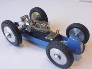
Anyway, it made a very attractive and intriguing project, and must be just about the smallest possible car into which a Mills 1.3cc engine can be crammed. I used some new repro Peri scale type 2 ¼" tyres as the rear drive wheels on the engine to replace the perished Frog originals. The drive side has a brass flywheel type wheel, and I made up an aluminium wheel with a ball bearing to fit on the non-driven shaft. Artypole (Peter Hill) provided a pair of 1 7/8" diameter scale Continental tyres from his spares box for the front end, and I made up a 3mm diameter axle and mounting plus aluminium wheels to suit, fitted with ball bearings. The fuel tank is an early, small Perfect control line tank, mounted ahead of the Mills engine. I didn’t fit a fuel cut-out, but there is just about enough room left to shoehorn one in had this been desired.
 |
 |
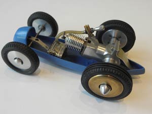 |
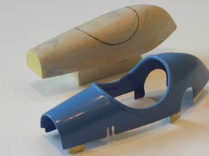
To complete the car, making a top body part was a bit of a challenge, so I thought about this for about 5 years! I decided to make the smallest and thinnest body possible, in line with the pan’s super lightweight style. The plan elevation shape is defined by that of the bottom pan, and the side elevation by continuation of the line of the nice front radiator cowl, so it just remained to draw up the rear body side elevation outline to fit over the Mills engine with minimum clearance and to fair into the point of the rear pan. It became obvious that a large cockpit cut out would be necessary to permit the engine to breath, cool and permit access to the venturi intake and fuel needle valve control. Not having the skills to beat a body out of thin aluminium as no doubt the original model engineer who made the car would have done, I carved a block balsa body plug to this shape to fit the pan and sealed the surface and waxed it, then laid up 3 laminations of 2 oz. glass cloth with epoxy resin draped over it. After curing, this was surface sanded and given a further coat of epoxy finishing resin, trimmed back to the edge line of the plug, then the moulding carefully prised off. The hole for the cockpit was then carefully sawn out to shape and edged with some fine rubber tubing, and some internal strengthening strips of 1/32" brass were epoxy glued to the inside top body edges and to form some mounting tabs to fit snugly into the inside edges of the bottom pan.
 |
 |
 |
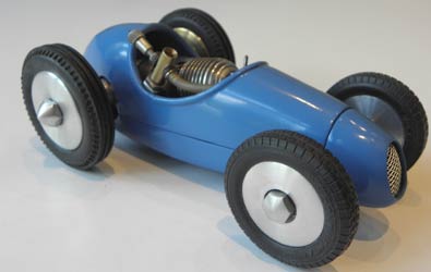
The finishing stage needed a bit of filling of the dents and rivets in the hand beaten body pan, then the top and bottom parts to be sprayed externally and internally with several coats of grey cellulose primer rubbed down to provide a smooth surface, and finally about 10 coats of Light French Blue cellulose lacquer sprayed on and rubbed down between coats to finish.
It has all made up into a quite handsome little beast, don’t you think? I decided not to fit a pan handle or bridle attachment points as I’ve decided not to run the car (as I have made plenty of other models to do that with), though this could be done with a bit of ingenuity, as it has been designed and engineered to be perfectly capable of functioning on a track in anger if desired at any time.
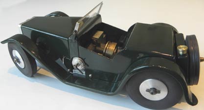
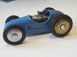
Steve builds a model of a 1927 Delage
I've just finished my latest tethered car project, a 1927 Delage GP car. The story behind this project is as follows:
Around January this year I was trying to find a nice tethered car project for my SAM 35 TCIG car pal Paul Butterfield, and he mentioned that he had a vintage clockwork model of his uncle's Delage GP car on his shelf, which he liked a lot. I found a 3 view drawing on a web search, and had Derick Scott print me out enlarged copies to suit 3.0" and 3.5" wheel diameters, Paul wanted to use an ED Mk 3 2.49cc front rotary diesel engine with an ED clutch and a 1066 gearbox he had, and it turned out that it wasn't quite possible to cram these into the body outlines for the 3" wheel size, and so the 3.5" version was selected.
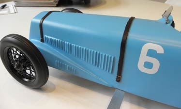
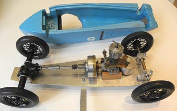
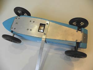
As this was to be Paul's first tethered car build from scratch, the construction was kept as simple as possible, with a flat 1/8" ali plate chassis and a one piece 6mm diameter rear axle running in MFA bearing blocks. The body was built up from 1/4" obechi sheet sides, cracked at the cockpit position, with hard balsa top and solid balsa rear body piece all bandsawn to shape, and as I was making a "kit" of these parts for Paul, I decided to make up two to build one for myself as well; who could resist such a nice vintage design? Exactly the sort of model I love to see trundling sedately round the Buckminster car track, a diesel engine smoking in the cockpit and simply rattling along with no suspension, and easy to get going because of the clutch, so no push stick starting - lovely, and very relaxing. I've added some detail like a windscreen, name badge on the radiator, non-working bonnet straps and a petrol cap but not added any cockpit detail. I would have ideally liked instruments or a steering wheel but the engine position precluded this.
I won't bore you with construction details here, this is made in a very similar fashion to my "Come in number 35" simple car construction article with a Cooper Climax T60 as the subject.
I painted mine in a nice light blue cellulose colour, trying to match as closely as possible that of an original Bugatti 35 which really caught my fancy when I saw it racing at Angouleme nearly 20 years ago, and I think it looks great, so I hope that you do too.
 |
 |
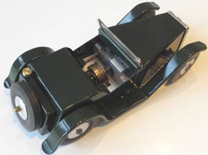
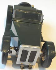
| All those louvres? | Plate chassis |
Paul is now about 80% through his model, and I can't wait to be able to see the pair of them together and running on the track later this year, when I have recovered from my imminent spine surgery and can get about again.
 |
 |
 |
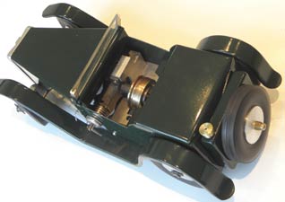
| Chassis concealed within body | ED MkIII with original ED clutch | Mike Day/1066 repro gearbox |
I would very much like to be able to make drawings for this model available at reasonable cost through the Derick Scott/SAM 35 Plans service, so that we can encourage others to make one of these nice old cars. I can make available my original marked-up drawing and paper templates and a photo file of the construction through its phases if anyone has a contact who would be able and prepared to do this, as I no longer can?
©copyrightSteveBetney2026