|
Home Updates Hydros Cars Engines Contacts Links ←Previous 2013 Next 2015→ |
|
|
Oliver Monk 'Workshop Ramblings' 2014 |
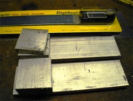
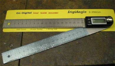
Last year I made an electronic device for checking engine timing. I bought and sold a couple of the electronic parts to fellow drivers, unfortunately not saving one for me, so when the time came to make one for myself, they were no longer available. I could not find one anywhere. I then had a bit of inspiration. We use digital angle measuring rules at work and they rotate through 360 degrees. The picture below shows the one I bought plus the cut up metal to make a digital timing device.
|
|
|
|
Not the best pictures but they show what I have done, all fairly straight forward. Technical Details
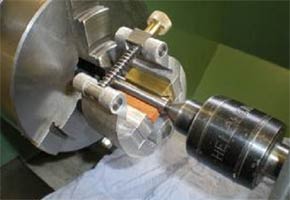
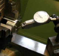
Jan-Erik has been guiding me in making pistons for my 2.5cc engine. I had got two pistons made, but they just needed the circlip groove putting in. The groove needed to be 0.45mm wide and 0.3mm deep. This had me beat, well beyond my cutter grinding skills but my local friendly expert gave me a few options although these did not work. The pistons were on hold.
 |
 |
 |
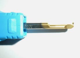
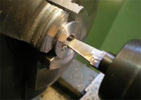
| I found a Tiny Tools groove cutter in tungsten carbide with a 3mm diameter shank and cuts a 0.7mm wide 0.4mm deep groove, a bit of work on the cutter grinder had it to the right width. | The ground cutter
on 5mm squared paper |
|
|
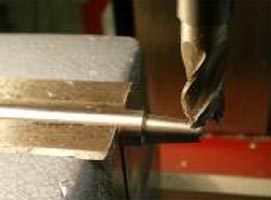
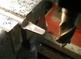
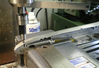
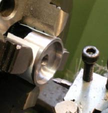
The lathe set up to machine the groove in piston. It turned out much easier than I had expected. With second thoughts I should have held the piston-holding-pin in a collet chuck, then I could have used it again. I will never get it concentric again in the 3 jaw chuck. At the back end of last season I ran the 2.5cc car with a new aluminium pipe without much success. I put the steel pipe back on and ran it again, but it had the same problem although putting on bigger tyres solved it. So, for this season, I am going to try the aluminium pipe again. |
|
|
|
|
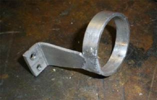
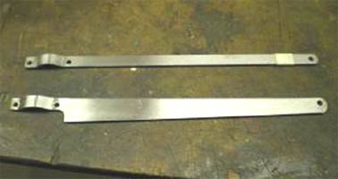
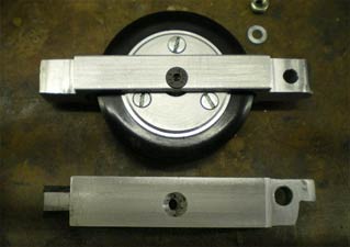
To get the balance of the car right with the aluminium pipe I had put a lump of lead in the back. Not a good solution, a new tether arm was required. To find out how much I had to move one of the hold down bolt holes, I hung the car up and moved the arm until it balanced. |
In the picture above you will see it was about 1mm. I made the new arm out of titanium that I bought at the World Champs in Switzerland. The picture on the right shows the new arm fitted to the car. I had another surprise, the titanium was as easy to machine as I had been told, use sharp cutters, not too fast and cutting lubricant.
That's it for this month, only four months until our first race in Hannover.
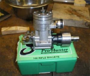
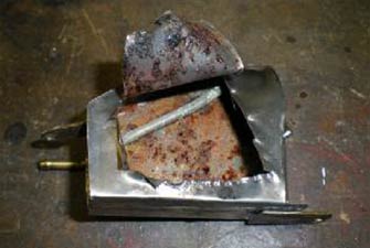
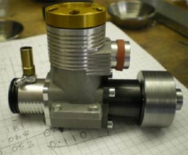
This is the unknown engine from my 1.5cc car. I asked in one of my ramblings what it was and have had an email from Gabor Dobrocsi who says it was made by Vladyimír Kríger around 1992.
 |
 |
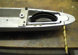
A little more progress has been on the car's rebuild. Made a clamp to hold the pipe in place and used some of the aluminium solder to join the two parts together. The metal work is about done and it all turns over nicely. Just needs a new top with a built in skid so it will meet the current rules but the weather needs to be a bit warmer so I can lay up the glass and resin and get it to cure.
 |
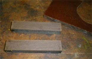 |
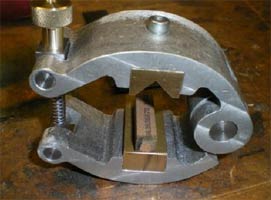
I had a set of castings to make an external hone bought for me as a Christmas present. On the left is the finished item. The plan is to use it lap pistons to final size, rather than use a stone as the abrasive. I intend to use 1500 wet and dry paper. Instead of the brass "V" block, picture on left, I am going to use Tufnol, glued together and the "V" machined in. I will let you know how I get on.
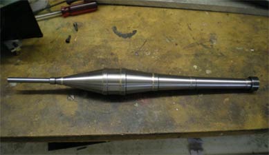
I have also bought some crankshafts for my 2.5cc engine and they have been left 0.005mm oversize so they can be lapped to get a good fit in the bearings.
 |
 |
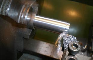
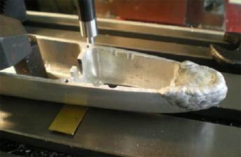
I have done a bit of work on the 10cc car as well. A couple of years ago I bought a big volume Swedish pipe, which I tried in Lyon with the MB10 but it did not rev. Did a few calculations and its now 15mm shorter, just cut a piece out and silver soldered it back in place. Only problem was it now didn’t fit between the back wheels! A gentle squeeze in the vice solved the problem.
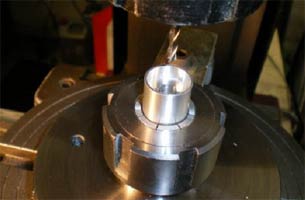
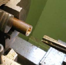
Just thought you might like to see the start of the piston making process.
 |
 |
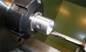
| Turn
the bar to the diameter required plus about 0.2mm long enough to
make two pistons. Part off drill and ream the gudgeon pin holes. |
|
 |
 |
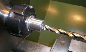
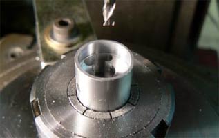
| Hold the blank in a collet chuck, drill out and bore the base of the piston, dimensions taken from the old piston. | |
 |
 |
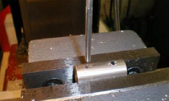
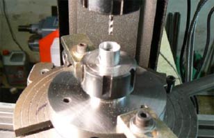
| Set up
in the vertical milling machine on a rotary table to remove the rest
of the material from the inside of the piston by plunge milling with a final cut to remove all the little ridges. |
|
 |
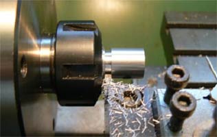 |
I use ER25 collets in my milling machine, lathe and rotary table. The collet chucks are not that expensive but they certainly make setting up easier. The last picture shows the piston being parted off. It then just needs facing off to length. I will finish the process off in a future write up when I fit the next piston into a liner. Thanks to Jan-Erik Falk for explaining the process and encouraging me to have ago at piston making.
It’s been a bit quiet in the workshop for the last few weeks’ pressures of work and routine things I have written about before.
|
|
|
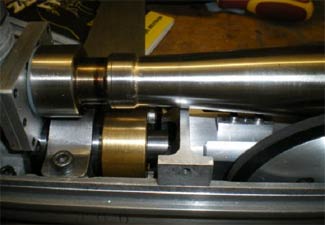
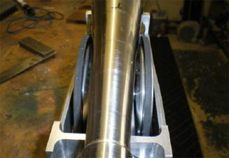
The picture on the left shows the crank for my 2.5cc engine being honed for final fit into the bearings, the little lapping tool I built worked very well perhaps needs a finer stone.
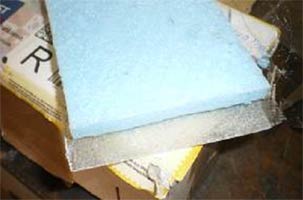
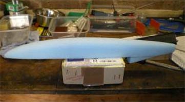
On the SMRU website Anders has been writing about his electric car build. He built the fibre glass body on blue foam. I managed to acquire some (above right) and had a practice run just to make sure it worked, the resin did not melt the foam. I cut away most of the foam from the glass then dissolved the rest with cellulose thinners, came up nice and clean just needed a rub down with wet and dry to finish.
 |
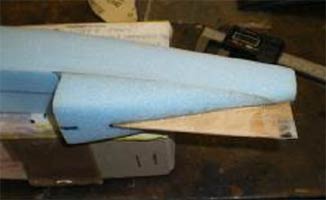 |
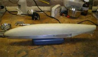
The new top for the 1.5cc carved out of foam, a card board template that was made to get the shape right and make sure the engine etc fitted in, and for the width I drew round the pan and made it thinner by double the thickness of the glass so it ended up the right size. It was a much easier and quicker than I anticipated making the core. On the right I have fitted the skeg with hard metal glued and glass covered in place.
 |
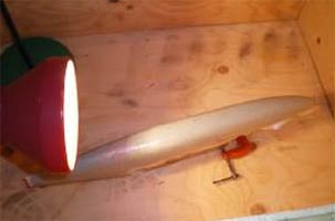 |
The first layer of glass has gone on the cloth is bias cut so it goes round the corners, and in my curing box as it is too cold in the workshop over night for it to cure. The glass is quite light 54g/m2 so it’s going to need a lot of layers.
 |
 |
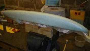
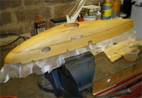
Part finished top on the chassis had a bit of a disaster put the moulding in the bottom oven of the range it got a bit hot melted the foam and distorted the top but as you can see it was saved with a bit of work, chassis with the hold downs being fitted.
As I write this, it is only a month to go before we start racing in Hanover and find out if the time in the workshop has proved worthwhile.
Now the warm weather is here it’s a good time to do the painting and fibreglass work without having to run the heating for long periods of time. I am banned from the house to do this sort of work.
 |
 |
| The Proto 67 old
timer car getting a covering of light-weight glass cloth |
The new body for the 1.5cc car getting a coat of filler primer. |
|
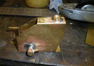
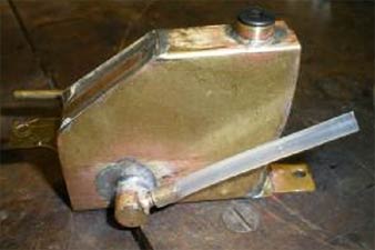
I had been setting balance of the 1.5cc car and I do this with a full tank of fuel also to check the running weight, when I emptied the tank little black bits came out with the fuel, dried castor oil I thought. I filled it with brake cleaner and left it a few days, more black bits lots of washes out still black bits. Decided to have a look in the tank, rusty, one of the problems with tin plate tanks, it looked really good from the outside. New tank required from the right material. |
|
Part built tank from brass sheet and the completed tank after cleaning out and checking for leaks.
 |
 |
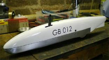
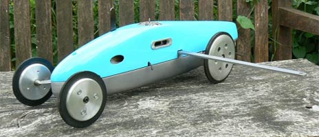
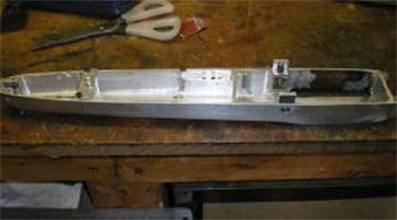
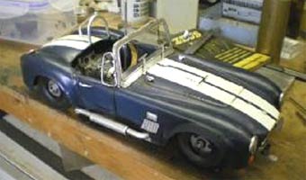
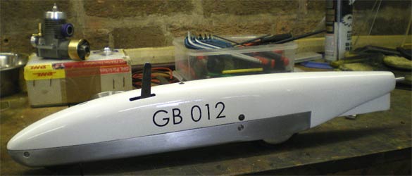
The little car is finished and complete with Aaron’s racing number on it. It has been an interesting project but with hindsight I would have been better off just using the engine, gearbox and wheels and making a new chassis for it. It has weighed in at 945 grams which brings it in nicely underweight and significantly lighter than when I first got the car.
|
|
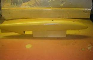
The making of the top has probably been the most satisfying part of the project the blue foam method is certainly better than making plugs and moulds. The proto 67 now has a coat of filler primer and is rubbed down ready for the final colour. I have some pdf files of Super Tigre transfers and have bought some water-slide transfer paper that I can print onto and make my own transfers to finish the car off. |
|
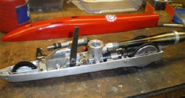
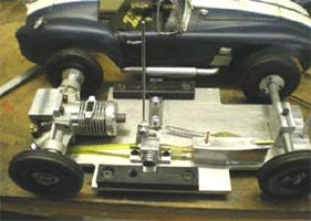
The plan for the summer was to go fishing and just do a bit of maintenance on my 2.5cc and 3.5cc cars. Both cars came back from Kapfenhardt needing very little work, the 2.5cc car just needs a new liner/piston and the 3.5cc I just need to figure out why it won’t accelerate beyond 180kph. Aaron’s 1.5cc car has turned out to be a bit of a project as you will see. |
|
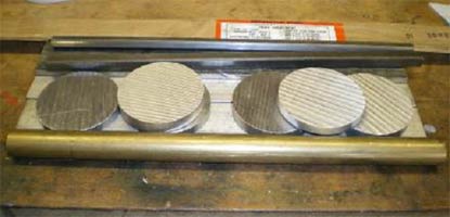
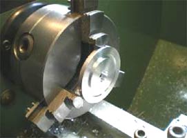
After Kapfenhardt I purchased the metal in the above picture, which will be turned into wheels for the 1.5cc car. We could not find any tyres that fitted the existing wheels. Also heads and a tether arm for the 1.5cc car.
 |
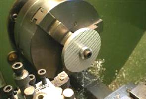 |
Jan-Erik Falk gave us a bag of new tyres. The pictures above show the new wheels being machined, a fairly straight forward turning job. You will see on the right hand picture that the blank has been turned round to machine the other side and it is held in place with a bolt and washer. I will do the bulk of the machining like this as I can take big cuts without the work moving on the mandrel.
 |
 |
The left hand picture shows the bolt and washer has been removed and the previously split mandrel had the expanding bolt fitted. On the right, getting close to the finishing cut. I use these expanding mandrels a lot to hold work concentric and have covered making them in previous ‘Rambles’.
 |
 |
The wheel having the holes drilled on the rotary table in the milling machine and the finished wheel.
 |
 |
I had to make hubs to fit the wheels to the gearbox and these required tapered bores. In the past I have tried to machine them but have never been very successful. One cut it’s a bit too small and the next too big.
So the solution is a D bit. These are easy to make from silver steel, which is a carbon steel that can be hardened. Picture on the right shows the bar with the taper machined on and about to be milled down to just over half its thickness.
 |
 |
Machined to half it thickness then it’s heated to red hot, quenched in water making sure it goes in vertically to ensure it does not bend. The cutting part is sharpened down to exactly half the diameter, I use a diamond stone, and finally tempered back to a light straw colour so it is not so brittle but still hard enough to cut.
 |
 |
A new bearing spacer has been made for the drive shaft as the other was a bit short allowing the pinion gear to move about. The gears are in a poor way and really need replacing. If anybody can recommend a source of spares, please contact me oliver.monk@btinternet.com .
 |
 |
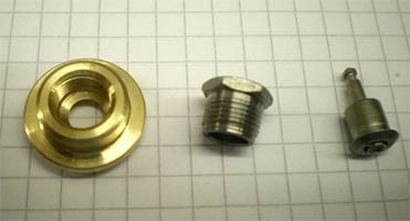
The car has a tendency to fly so a new tether arm has been made to apply some down force to the car to keep it on the track. The last job is new heads for the engine, the plug on right is the one that is currently used and not readily available. The plug on the left is a Nelson drop-in Globee this will be tried along with a standard taper seat plug.
 |
 |
The above project has been sitting about for a while so I have made the shut-off and a tank plus a few other bits so its finished and ready for a run out if I can get it to start, not much good with diesels. If it does not perform it could end up being a glow motor. Well that is it for this month.
|
I have finally finished the Proto 67 car and it is now ready for an outing. If there is room it may be going to Hanover for a run. It’s taken a couple of years on and off to build but has been an interesting project. Not sure what the next old timer will be? I have a few options, castings for an Oliver Tiger powered Shadow or Slabang. |
|
Both of these require fairly drastic modifications to the engine, not sure I want to do it an original Oliver. Could be another 5cc car on a German chassis, a similar era to the Proto 67 and I have a K& B 5cc rear induction and side exhaust motor that should fit the bill.
|
|
 |
 |
|
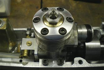
These pictures show the new head for the 1.5cc engine that uses a Nelson type globee drop-in plug. I will write up how it was made when I photograph the making of another head for the 1.5cc car. |
The head looks good in the engine. I also made another head with a turbo taper seat plug in, but it all looked out of proportion when it was in the engine. |
|
Aaron returned home late Sunday from Basel after breaking the existing British record in two of his three runs, and went even quicker in practice as you always do. Philipp Meier from Basel has taken Aaron under his wing and has been teaching him how to run these small cars and giving him a list of what needs doing to the car after each event. All the work to date paid off this weekend with a final run of 222,584 kph.
This is going to be a catch up of what’s been done over the last couple of months in my workshop.
 |
 |
Aaron’s 1.5cc car has gone well this season, but needs better suspension. It currently has springs with some rubber as the damper. Our local welder filled up the old slot and a new slot has been machined in, nice and square.
 |
 |
The new wheel carrier being machined up and it nearly complete. A bit
lighter than the old one.
 |
 |
The set-up for drilling the front pivot hole. It can be difficult working on a finished chassis, too many curves, not enough flat bits to clamp it down on.
 |
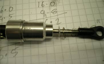 |
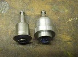
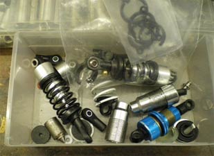
My box of old dampers, these are too big, but bits from these would be used in the front damper for the car. The picture on the right shows a damper where the "O" ring seals are held in place with a circlip. They don’t work on tether cars as the circlips pop out and it loses the oil from the damper.
|
|
|
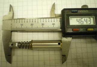
The picture above shows my solution to the problem and on the right the parts for the damper. The squares on the paper are 5mm.
 |
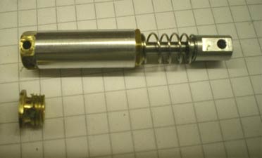 |
The completed damper. Unfortunately I couldn’t seal the threads and the oil leaked out of the top pivot hole. The second picture shows the solution.
 |
 |
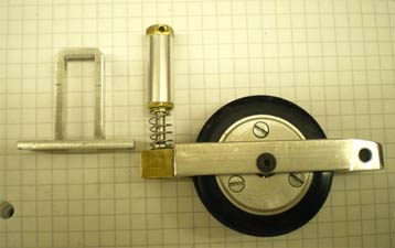
The completed suspension ready to fit, and installed in the car. It seems to work well as Aaron set a new British record in Pila in October.
 |
 |
 |
 |
|
|
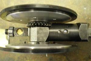
Made a flywheel and collet for my Gado 2.5cc engine I will race this engine next season in my current 2.5cc car.
|
||
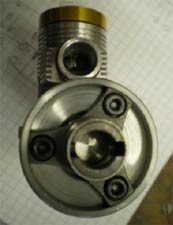
I have struggled all season to get my 2.5cc car to go fast, so I had a chat with Gabor Dobrocsi and did a drawing of his pipe so I could make one and try that.
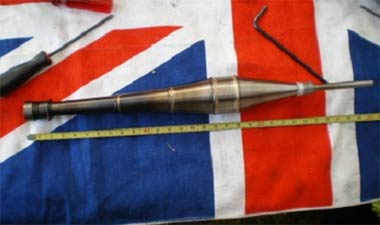 |
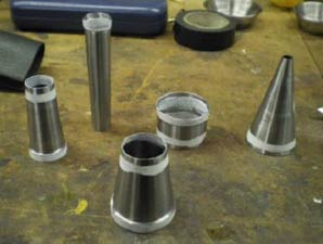 |
 |
| Original pipe being measured | Newly machined sections | Nearly done |
I machined the pipe segments from solid bar, the wall thickness is 0.3mm. The white on the segments is Tipex (correction fluid) to stop the silver solder flowing where you don’t want it to.
|
|
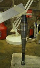
Left:- The finished pipe ready for a try when we go to Tallinn for the Lucia race. The season is almost over and thoughts turn to winter projects. Another pipe for the 2.5cc car to try for next season and perhaps a new car, either 1.5cc if I can get a gearbox or failing that a 2.5cc car.
|
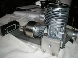
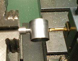
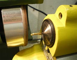
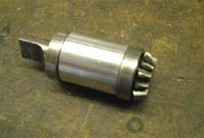
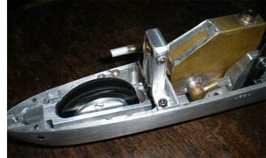
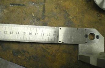
Digital Engine Timing Measure.
The details. June 2015
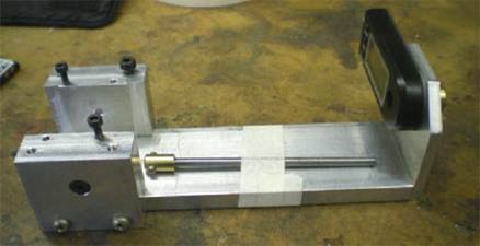
I have given an over view of the modifications of the angle rule to form the digital readout. No dimensions as they will all probably differ. The size of the frame depends on what size engine you are going to use it for, this one does my 10cc, 3.5cc and 2.5cc engines by using spacers. The drive-shaft taped on the rig fits the spider on the flywheel, and there is a grub screw to hold the shaft in the digital head.
 |
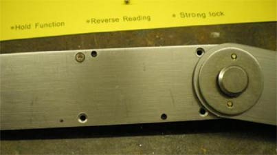 |
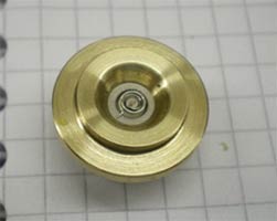
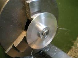
| The device is based on a digital angle measure, lots on eBay. Mine came from www.arceurotrade.co.uk | Take the chrome nut off the front of the device and remove the 4 screws from the back, there is a small nut on the front that has to be taken off. |
 |
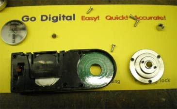 |
| These are the bits you don’t need, you can see the small nut in the picture |
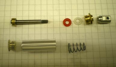
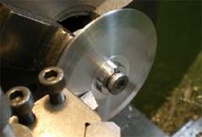
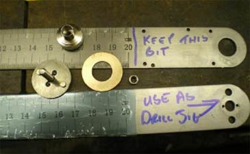
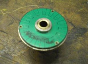
These are the bits you use. Note the two pins in
the chrome part they are used to locate the brass part |
 |
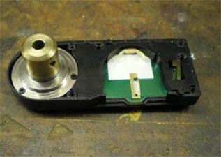 |
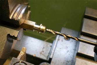
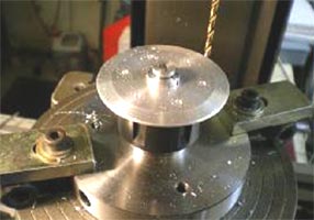
You need to bore out the hole in the chrome part
with the timing disc on to locate the brass part. Make the brass
part as per the pictures, just make sure it long enough to poke out
of the back of the rig to get the screw in. Drill two small holes in
the brass part using one of the rules as a jig, and stick it together
with Loctite.
 |
 |
|
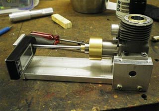
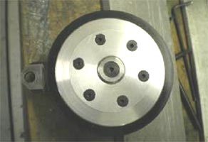
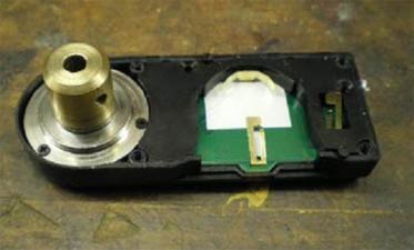
The modified digital unit ready for assembly back on to the cut-off rule, see picture below. |
|
 |
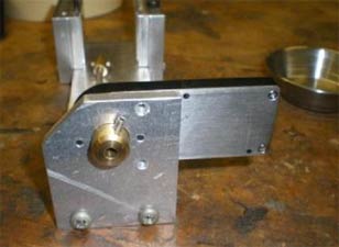 |
| One of the rules is cut down and forms part of the device | Note the grub screw to hold the shaft |
Any questions send me an email oliver.monk@btinternet.com
OFM May2015
©copyrightOliverMonk2015