|
Home Updates Hydros Cars Engines Contacts Links Contact On The Wire |
30cc Hydroplane Engine Development.
Or the growing pains of an engine, by Lionel Lawley
Lionel's original A class hydroplane and engine.
OTW. Throughout the long history of racing tethered hydroplanes one of the key elements was the ability to build and develop a competitive motor. Once commercial engines became available it allowed more people to become involved but created a great deal of dissent over the relative merits of ‘purchasing’ versus ‘building’. To cater for both camps some classes were restricted to home constructed motors and now there is a clear divide with the Naviga classes dominated by commercial engines and the British A and B classes the province of the individually produced motors.
There are many articles in the specialist magazines that describe in minute technical detail the building of model racing engines. There are others that outline the development of a particular engine throughout its life. Seldom is there to be found an article, which so graphically describes the trials and tribulations involved in designing, building and competing with a ‘home built’ engine as this contribution by Lionel Lawley.
We are indebted to Lionel for allowing us to use his material and to John Goodall for permission to republish the article, which first appeared in Model Engine World.
The two engines I designed and made some years ago for Class A tethered hydroplanes are shown in the accompanying photographs. Class A is the largest capacity class and embraces both internal combustion and steam engines. The only rules are 15-30cc for IC. Engines and a maximum all up weight of 16lbs, so a steamer can be made as large as the weight limit will allow. All engines are to be homemade.
|
|
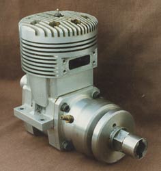 |
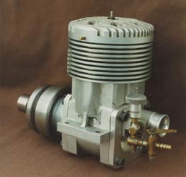
I have to excuse the appearance (of the motors) but they were designed and made for a purpose. That is, to produce the maximum power and survive-not to look pretty in a glass case. They have each had considerable use. Robustness is obviously a requirement and some top Japanese racing motors have suffered structural failures when used in a hydro. All machining was conducted on a Myford S7 lathe. The first engine is the one with the large circular fins. It was triggered by my brother experimenting at work on an official project to produce aluminium castings by using expanded polystyrene as the pattern material. The opportunity was there to obtain appropriately shaped blocks. 30cc Mk1 built in 1978 |
This engine was completed in 1978. The porting was based on the early OPS 60 with a dash of road racing MZ 125! It featured an unhardened steel liner and a piston carved from solid aluminium alloy that carried one cast iron piston ring (ex Reeves). The connecting rod was again alloy, bronze bushed at the small end and a Torrington B66 crowded roller big end running on a hardened crankpin pressed into the steel crankshaft. The shaft was made from an old JCB ram liberated from a local skip and ran in two ball races. Induction was through a rear rotary valve with Tufnol disc inside the case similar to an ED 2.46 set up, except that the disc was fitted to its own shaft running in two bronze bushes in the back plate. As can be seen, not very high technology and made from what was available.
A fair number of teething problems were experienced, my only previous engine building being a Westbury Atom Minor, so this was new territory.
The first serious attempt at a run resulted in the con rod small end letting go. My two elderly assistants both ran cross flow scavenged 30cc engines, which tend to accelerate in a leisurely fashion giving plenty of time to immerse the propeller and so load the engine! My Schnuerle ported engine went from nothing to a lot very quickly and before we got the prop in the water, it was all over.
The engine was solid with the forked remnant of the rod small end jammed in one of the lower transfer ports, the only sound being the flywheel spinning on its collet after being freed by the sudden stop. What I had thought of being high strength alloy obviously wasn’t. Since then all con rods have been made of steel and there have been a few of them. At least they do not break any more, just bend into an ‘S’ shape when the engine ingests water, as the result of a bad launch, or from taking a dive!
|
|
With a
new piston and steel rod, the next problem was vibration. From a very smooth
engine it was now frothing the fuel in the fuel tank and preventing a decent
run, so I resorted to heavy metal slugs in the crank disc, there being no more
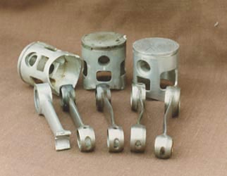
space for metal removal adjacent to the crank pin. I tried various washer types spacers on the crank pin to control big end movement, but irrespective of the material used they always disintegrated and went up through the transfer ports, usually to the detriment of the piston. Left: Selection of Mk1 and Mk2 connecting rods and pistons |
At one meeting the engine achieved over 80 mph and won, with a substantial flat on one side of the piston. I hadn’t time to make and run in a new piston prior to the event. The final solution to the big end problem on this engine was to replace the crowded roller with an INA 10mm. caged bearing on an appropriate sized crankpin.
The engine also suffered several seizures until I established the correct piston clearance, so I had plenty of practise lapping the cylinder bore clean.
This engine, at its first competition in 1981, established a record of 76 mph. not much above the previous figure. With the above-mentioned modifications it eventually recorded 92.4 mph during 1984, which seemed to be its limit. A succession of tuned pipes got it turning up to about 16,000 rpm. Subsequent calculation indicated that the porting of transfer and exhaust were both optimised for 12,000 rpm. peak, which explained why it was gasping around 16,000.
Having become aware of a method for determining approximate
port sizes and timings for particular power characteristics (although not in the
same league as Gordon Cornell’s methods) Mk II was laid out, again aiming for
a widish power band. Incidentally, the Mk I was capable of going from an
unassisted hand launch (5 mph?) to 93 mph. pulling steadily all the way until
the tuned pipe came in when the acceleration improved rapidly. During the mid
1980’s catapult assisted launches were introduced, which allowed the use of
narrower power bands.
Mark II
|
|
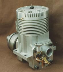
Two friends from my model aircraft club came forward with chunks of cast iron and aluminium alloy, courtesy of, but unknown by, their employers so this engine was carved out of the solid. It is heavier than it need be, but it is rather tedious removing unwanted metal on the Myford. Despite a certain amount of scepticism from the experts regarding calculation of port sizes, this engine was more powerful than Mk I and was immediately up to the mid to high 90s. This however highlighted another problem-vaporisation of the plastic big end cage, much to the amusement of other competitors. The jangling noise only stopped when a roller jammed between the crank disc and case. Only seven and a half rollers were left inside the engine, yet the piston was unmarked on the side, although well peppered on the crown. None of the other rollers were ever found. |
The bearing overheating was resolved (so far) by rotating the back plate to place the inlet at 12 o’clock and modifying the disc drive so that the fuel was sprayed directly on to the bearing. The main bearing was also modified. There was evidence that, due to differential expansion, the bearings were sliding on the shaft and slackening the fit. So the inner bearing was replaced by a roller bearing and the outer was now retained in the housing by a clamp ring for shaft location purpose.
In this condition the Mk II established a record of 108.77 mph. in 1989, which stood for about 11 months, but the speed has since been well decimated. The above speed was beaten by two glow motors, one a conventional ringed motor at around 122 mph, this engine was also the first to officially exceed 100 mph. in Class A and the second an AAC lapped piston engine at 124 mph.
Three flash steamers have also beaten my speed, two at around 113 mph and the other at 118+ mph. They are really impressive to see. There are two more close behind, each capable of about 100 mph.
As a final observation, the steam engines are about 11cc, whilst they weigh almost the full 16lbs, against the 30cc two-strokes at an all up weight of 10-12lbs. So comparing power per cc (and forces inside the engine) the steamers are way up on the two-strokes, whilst not forgetting that the two strokes are still more powerful than any commercial engine of similar size.
If any readers are interested in building their own engines which perform as opposed to run, then I can recommend tethered hydro racing in either the 15cc or 30cc classes, both restricted to home made engines. Your engine will run on its own, against the clock, for 500 metres and thus will be a true record of its achievement. Why not come and show us how good your engine really is?
|
|
|
|
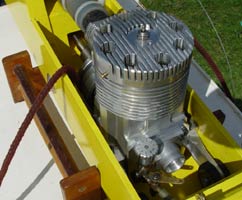
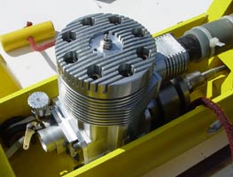
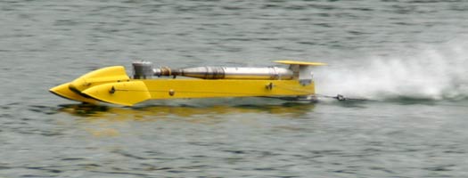
OTW. Since this article was originally published in 2000 Lionel has continued with development of the engine. Speed has risen to 118 mph, which is tantalisingly close to the fastest recorded by a flash steamer at 120.92 mph by Bob Kirtley's Pisces II
in 2005. For the 2007 season an entirely new hull has been built. Lionel is shown above talking to Bob at St. Albans. The photo's show the new boat with details of engine and installation.Subsequently Lionel came to the conclusion that the new hull was not working as he had hoped so the original was dug out and refurbished. With the engine back in the old hull it was not far off its previous best speed when disaster struck and the steel conrod broke at full revs comprehensively wrecking the motor. Unable to repair it for the 2015 season Lionel retrieved the original engine and ran that for the entire year.
©Copyright Lionel Lawley 2006