|
Home Updates Hydros Cars Engines Contacts Links Contact On The Wire |
Rebirth Of A Maserati 4CLT
John Goodall
At the SAM35 Octoberfest swapmeet in 2023 an old customer of mine and reader of my MEW magazine John Hemmings offered me an incomplete scale model car body showing signs of its apparent age. We agreed an exchange of one of my rarish engines for the body, which at the time I knew nothing about at all, except it was an Italian Maserati. John told me he had been given the body by an old friend of his who was now aged over 90 who had owned it from new, but done nothing with it. John obviously knew I was now a tether car enthusiast.
 |
 |
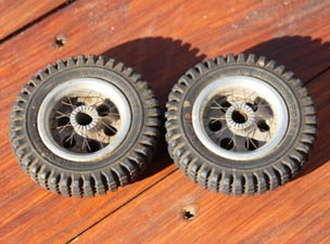 |
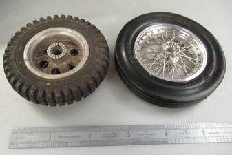
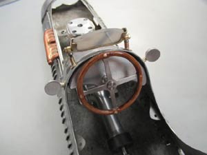
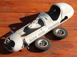
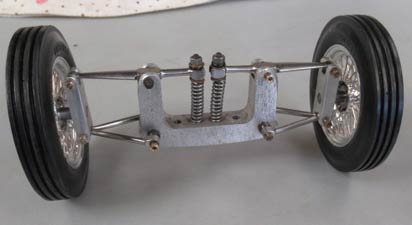
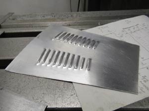
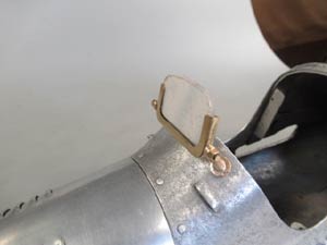
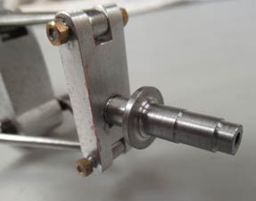
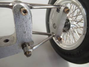
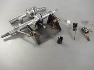
| Maserati body, louvres in abundance | ZN independent front suspension | Just two wheels |
In discussions a day or two later with Hugh Blowers of OTW he thought the body could have been made initially for purely static display during 1949 similar to one of those made by Rex Hays. It has double wishbone suspension at the front, which was missing uprights and the axles and the entire rear suspension, as well as the bonnet, which was also missing. Hugh thought ZN, a firm long extinct, made the front suspension. See OTW for all the background to ZN and their products. This suspension was actually made for a tether car, as it has no swivelling axles unlike the static version, which has. The body is highly detailed with copious ventilation louvres cut into the body as per the full size car, which I had discovered was the Maserati 4CLT model originally made in 1948 only a year before the model. The car was powered by a 3 litre eight cylinder engine made up from two four cylinder 1.5 litre units joined end on, which is why there is a gap in the exhaust manifold centre. Henri Baigent had also made a very similar model to this one?
|
When I got home from Buckminster I looked out a set of wire wheels I had bought off Steve Betney some years previously, that were surplus to his needs. Chris Garcia in USA made these and Chris has since stopped making them but I thought they might come in useful to me one day, in spite of their high cost. That day had now arrived because they looked superb and matched closely the full size car and are runnable, so I knew I had to use them on the Maserati build. The model dates from 1949, which is why corrosion was now so evident on the 76 year old body. It comprises about sixteen different panels and doublers, which looked to have been pressed in dies all hand riveted together into a superb piece of work. I carefully rubbed the body down with fine abrasive and finished with wire wool, it did look better, but deeper pitting remained. |
|
I set to and milled the front suspension uprights from H15 alloy to the drawing sent by Hugh but when I offered the second up it leaned out at a peculiar angle? I measured the upper and lower arm centres and there was an error of 0.060 of an inch (1.5mm) between them? Checking the lower bush it was just large enough to make a new eccentric bush to the error noted previously and now both looked vertical and matching. Quality control lacking at ZN perhaps?
 |
 |
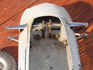
| ZN front suspension with new uprights | Complete front suspension, no brake drums as yet |
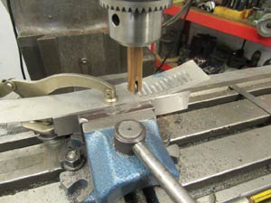
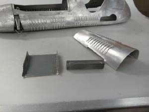
I next decided to make the missing bonnet and I had to learn how to do this and make the necessary tooling. Hugh again turned up an article by Arthur Weaver, which showed how it could be done. It turned out easy to make the tooling, but more demanding to produce the louvers. These had to be cut using a shaped roller to a length differing by 0.050 of an inch or 1.25 mm to match the bodies narrowing taper. I achieved this on my Bridgeport milling machine using the X-Y digital readout to control length of cut and spacing and by using the machine manually only. I started each of the louvers parallel to the outer edges. A few practices later I cut the first side and repeated this on the opposite side to match, this all done while it was still flat of course. I made a tool to shape the exhaust cut out raised edge matching the body cut-out and its raised edge almost exactly. The bonnet was then bent by hand over a suitable piece of pipe to match the body shape.
 |
 |
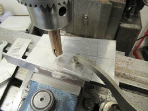 |
| 'Arthur Weaver' system for cutting Louvres | Trial run | Set up for the bonnet |
 |
 |
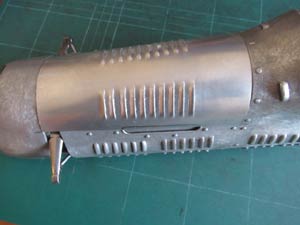 |
| Bonnet before rolling | Tool for forming exhaust cut out | Bonnet in place |
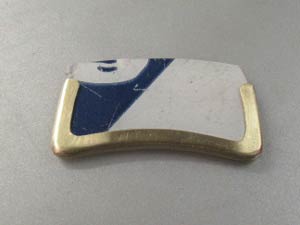
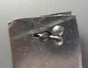
I made the six bonnet catches from brass, which were initially turned and then finished by hand filing to a streamlined shape. The rear two are fixed to the removable cover while those at the front work similar to full size to allow bonnet removal. They are nickel plated to finish. At the same time I made the dummy filler petrol tank cap from brass held from underneath by a single screw and the breather in SS. Soft bright steel clips were made to hold this in place set after painting.
Dummy rear view mirrors were made in alloy freehand turned to correct shape with 8BA screws and brass support necks these were nickel-plated. The windscreen surround was made by two L shaped brass beatings which when placed together and silver soldered formed a U shape with 2mm gap to take a screen made from 2mm polycarbonate.
 |
|
 |
| Bonnet catch | Windscreen frame | Windscreen and mounts |
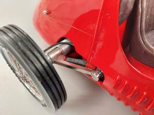
Hugh Blowers also provided me with copies of period articles on building this highly detailed model. That enabled me to make the front axles turned up in my lathe. The Chris Garcia wire wheel hubs are very small in diameter and I managed to find two ball bearings that would fit one each end of the hub giving a stable mount to the wheels when all were mounted on the axles. I turned up dummy brake drums and back plates were fabricated from two pieces of aluminium with mesh debris guards trapped between the two pieces riveted together. I added dummy hydraulic hoses made from O-ring rubber.
 |
 |
 |
| New stub axles | Rocker arm and lower wishbone | Brake drums and brake hose |
My plan was to power the model and I determined a single cylinder engine would be far too bulky to fit under the bonnet and I tried a CS in line twin I had which with a little modification could be made to just fit with nothing to spare. I was averse to fitting a foreign engine and preferred an Oliver however and my preferred British alternative for a British made car was non-existent. One of my builder friends of special engines had unfortunately and sadly recently lost his wife and a more recent contact proved too have too much other work so that after some months there was no visible progress at all. This held further work up for several months because without the engine other things could not be decided or completed.
I modified a bevel gearbox casting set I had of 1066 origin using a set of 2:1 ratio bevel gears bought economically from Belting On Line. The gearbox housing needed widening to match the front wheel track at the rear. The cast originals had to have a short piece welded on each side by my friend Ian Harper. These were than bored and reamed on the lathe to suit an extended rear axle made from tough steel, as was the pinion shaft. I found a suitable coupling among my spares to take the engine drive.
|
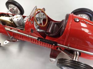
I could now concentrate on the rear suspension. I wanted this to be as close to original as possible and made up the swing arms in mild steel silver soldered to steel bushes which held the gearbox shaft housings, I added steel pockets into which the multi leaf springs ends fitted and made from Phosphor Bronze. I made up a sub frame from light gauge steel to which the swing arms would be pivoted. The centre of these pivot‘s has to be co incident with the coupling joint pivot exactly. The forward end of the springs were crimped into a bracket bolted each side to the sub frame inside the swing arms. The sub frame spreads the suspension load's widely on the fragile body. John talks about his work on the car go to www.youtube.com |
|
Part two:
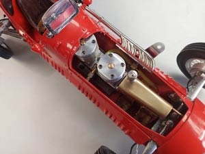
I had previously bought two new Oliver Tiger cylinder assemblies off Steve Fardon to facilitate the build myself, but crankshafts were not within my comfort zone. I can still do straight forward milling and turning being a Toolroom Turner by trade, but my age of 86 is not helping my current abilities and expertise, which have definitely deteriorated. I approached Steve Fardon who now owns John Oliver Engines to see if he would make the crankshaft‘s for me and after some consideration, he very kindly stepped in and offered to make the crank case as well, saying he preferred to do the lot to ensure compatibility. He made a superb job with which I am very pleased. It has a 180-degree rotary valve between the two cylinders, feeding each in turn with alternate firing. I had sent Steve a sketch I had made some time previously of the layout of the crankcase and the extra long front shaft to connect direct with the gearbox coupling. The base-mounting flange is sloping to line up with the coupling and has a very wide base to spread the weight and loads in the fragile body. I collected the engine from Steve on 17 July 2025 and could now get on and complete the rest of the car.
 |
 |
 |
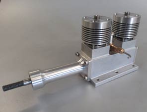
| Modified 1066 axle and mounting | Twin by Steve Fardon | Complete motor and drive train |
The rear wheels and brake drums mirror the front ones with some changes due to the axle housings larger size and the need to drive the rear wheels from the axle. I made adaptors in steel slotted and bolted to the wheel to accept a pin drive at each end of the axle. This allows the wheel to be pushed on tightly over the pins, so it can be removed if need be in future. The dummy hydraulic hoses again from O-ring rubber were placed on top of the axle otherwise they would be mostly hidden by the larger size of the axle housing.
|
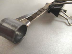
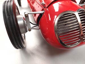
Other work completed while waiting for the engine was to make a dummy exhaust, which I filed up from a piece of brass, which would be nickel-plated to finish. There is a gap midway between the eight exhausts as per the two-engined full size car. The tailpipe is stainless steel tube. The grill presented a lot of problems and I started by making a surround in SS with SS wire bars, but silver soldering was difficult even with an expensive acid type flux, I think due to rapid over heating caused by the thin metal? I also tried German Silver, but did not like the yellow tinge, so I ended up using brass which I know will silver solder OK and had this nickel plated. A dummy radiator sits inside the grill made from expanded metal stainless steel to hide the front suspension structure and it does enhance the look. |
|
|
|
The cockpit I felt needed to be fully detailed to make it compatible with the rest of the car, but it is compromised by the engine front bearing housing of an inch diameter, which sits directly under the seat area, a scale size of 10 inches no less?? This unfortunately raises the seat floor and I had to make the seat slightly smaller than scale to fit in. The seat squab height pushes up the steering wheel, which like the seat I had made during the time the engine was delayed. The seat has an aluminium pan and curved back with balsa lining and is covered with very thin leather found on eBay. I used this to make a headrest in very similar manner with plywood backing screwed to the bulkhead. |
Turning to the instrument panel I again wanted this to look as close to scale as possible, but could not find any suitable commercial items. I decided to buy some full size replica instruments made in India photograph them and get them reduced to the scale size I wanted by a local print shop and this gave me the correct type and face colour of the originals. The new unused instruments are now for sale £30 only? The prints were mounted on thin plywood with a clear face of polycarbonate 1mm thick, They are set behind a hand beaten alloy dashboard with drilled holes for the instruments on which I simulated engine turning by using a fibre glass cleaning/scratch pen turned in the pillar drill, It can be done by hand as well by twizzling the pen carefully keeping it in one spot I discovered.
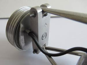
The fuel tank was made up from brass, soft soldered together in the usual way with the filler adapted from a Schrader inner tube valve with its valve cap. It is mounted in the engine bay in front of the engine. Three mounting brackets were bent up in brass and silver soldered where folded and the fuel cut off is an original Healy rotary type I have had in stock for some years. The cut off arm can be removed for static display or in transit.
The final parts to be made were the two tether arm brackets, which I fashioned in stainless steel. The front one is fixed to the four front engine bolts of which there are six and the rear one to four of the sub frame bolts, which directly support the loads of the two main weight centres. It also helps the body to distribute and support them better I believe.
One of the last operations was getting the painting done and I again turned to Peter Dumelow and his son John, Stove Enamellers in Branstone Road, Burton upon Trent. I have used them for many years on my vintage motorcycle restoration work; they are very obliging and very good. John usually works on my model cars and he restores Austin Pathfinder pedal cars as a sideline. I have made many replica parts for him. Both are keen full size car enthusiasts and are sympathetic to my models. They have two or three cars in the works at any one time. John lightly blasted, etch primed and stove enamelled all the parts I sent in Italian racing red, which sets the car off very well I think.
In hindsight I underestimated the assembly difficulties some of the above items would present. They proved exasperating; time consuming and very awkward, made more so by not wanting to damage the paint finish. I had to make special tubular slotted nuts behind the dashboard and rear view mirrors to get them into the confined spaces. A special short screw driver was made to fit the cramped height, with a brass tube collar to stop it slipping off the slot in a space I could not see into and could not get fingers into either, so a lot done by pure feel alone. Installing all the cockpit 8BA screws, twelve altogether, making the tooling and eventually fitting them satisfactorily took over four days, rather than the 15 minutes or so it would normally take. Patience is definitely needed, but it is extremely rewarding now it is all finished.
 |
 |
 |
| Cockpit | Grill and radiator | Rear suspension and radius arms |
 |
 |
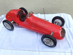 |
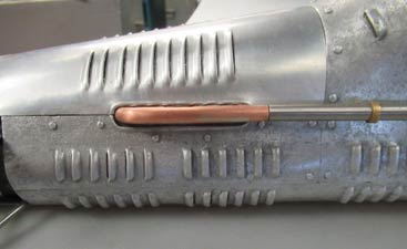
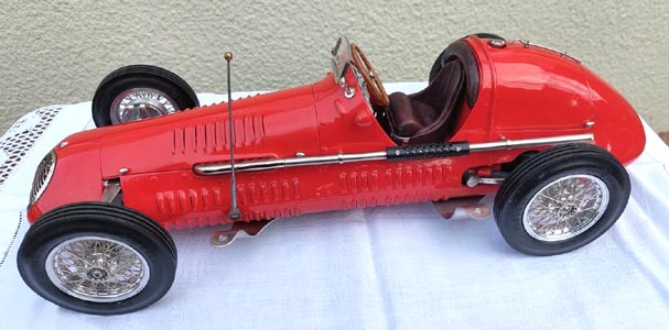
| Fardon 'Oliver twin' | Exhaust, heat shield, fuel filler detail | A beautiful model |
©copyrightJohnGoodall/OTW2025