|
Home Updates Hydros Cars Engines Contacts Links Contact On The Wire |
A
renovation and more
Dougal McIntyre
|
|
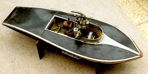
OTW: A while ago an email arrived asking if we could identify this vintage hydroplane that had been in the current owner's family for many a year? It was a very nice looking 1930s boat shaped, slipper stern, single step hydro with a well engineered four-stroke motor. The only information at that time was that it had been run in Scotland but, despite much poring over Model Engineer magazines, we could add nothing further, although we were able to offer advice about restoration/renovation. In the course of subsequent emails, the current owner, Dougal McIntyre, explained that he intended to restore the boat, and gave us an intriguing glimpse into what he knew of its history, which although not helping to identify the boat has led to further thoughts about its origins? |
|
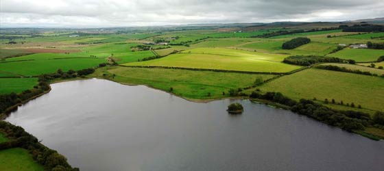
He clearly recalls the boat being run by his father David in the late 40s on a tether in a small pool at the family home and allowed to run free on Martnaham Loch. Inevitably it stopped out in the Loch and with no dinghy to hand, had to wait until it drifted to shore to recover it. Right: Martnaham Loch in current times. The launch point in 1947 would have been at the far end and I seem to remember there being more trees around the waters edge. Although Dougal thought that his father had obtained the boat around 1947, subsequent investigation throws up what is possibly an even more intriguing connection relating to his father. |
|
David McIntyre has a significant place in the history of aviation and in particular, Scottish aviation. As an RAF officer between the wars David came to prominence, along with Douglas Douglas-Hamilton, by making the first ever flight over Mount Everest in 1933.
|
|
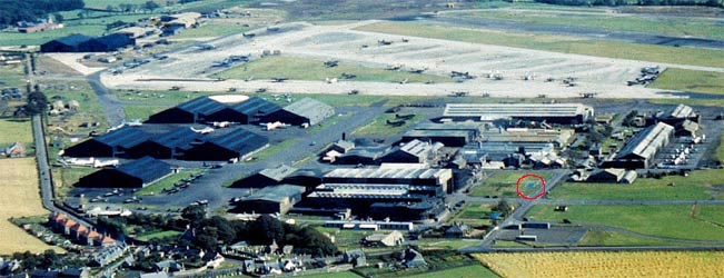
The epic story of this in open cockpit Westland Wallace aircraft is worth reading alone but it paved the way for a commercial venture that remains in the lexicon of aviation to this day. In 1935, he, along with Hamilton who later became the 14th Duke established Scottish Aviation Ltd on 384 acres of land near Prestwick. Left: Their premises were expanded significantly when the Palace of Engineering from the 1938 Empire Exhibition in Glasgow was dismantled and re-erected as the main SAL factory in 1941. Evidence has now emerged that points to the history of the vintage hydroplane being inextricably linked to SAL. |
Above: Late WW2 photo of Scottish Aviation Works at Prestwick Aerodrome with Palace of Engineering building in the Centre. Fire pond circled in red.
Dougal now takes up the course of the renovation. His original diary runs to 28 pages, so, with his agreement, we have précised it somewhat to illustrate the process and some of the pitfalls along the way.
|
I have a vague recollection that at one time in The Cushats pool it overturned and the cylinder head was damaged. Father had it rebuilt by the Apprentice School at SAL, and a one time apprentice at SAL recalls making new valves for a similar engine. The bow of the boat was damaged however when they tested it in the fire pond in front of the Palace of Engineering building at the factory. I do not think it was ever sailed after that. From then on it moved from house to house until 1962 before being consigned to my workshop cupboard until 2010 when it was taken out for photographing for an inventory. There it remained until Covid lockdown inertia caused me to record the detail of our collection of tools and toys for the benefit of my family, before my memory failed completely. The boat was taken out for restoration in early March 2022 and although pretty dusty after 75 years in a cupboard there were no apparent signs of rusting, which was encouraging. |
|
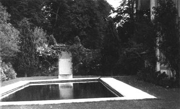
Above Right: The Cushats swimming pool in the late 1940’s. David McIntyre erected a Pole in the centre, anchored underwater at the bottom and supported by 4 guy ropes at the top to allow a round the pole line to be attached to the speedboat. The forces exerted by the prop and the ensuing wash made the exercise unmanageable I seem to remember.
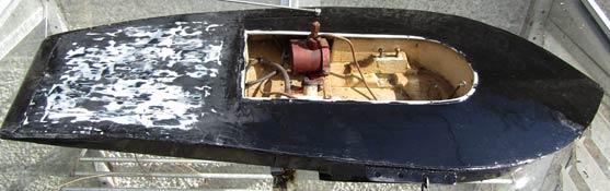
On inspection, it was evident that there were two damaged areas in the front, plywood decking as a result of the earlier accident in the fire pond. Also the rear decking had a large number of small cracks along the grain that would require filling before repainting. The hull appeared to be made from pressed or moulded aluminium sheet (a sure indication that an aircraft firm was involved somewhere, as this mirrors construction methods seen in other boats built using aircraft material and parts). This had been dented quite a bit and would also need filling. Excessive layers of paint on the underside had caused cracking and would need to be dealt with. A number of the dents were down to the use of countersunk brass screws used to fasten the superstructure and fittings in the engine bay.
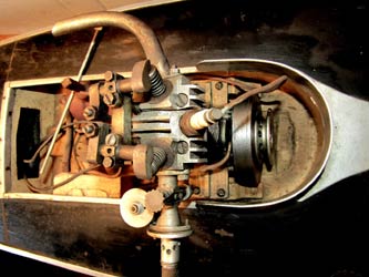
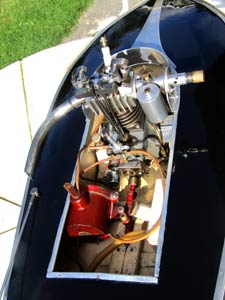
The skeg and prop seemed in good condition but no sign of a battery although both leads were still connected to the engine and ignition cut-off. The fuel tube was so hard that it had to be cut off to remove the engine. I remember the tank being pressurised by a rubber bladder in the rear compartment after inflation and the rubber pipe to the tank with a brass connector was still present. A plate for attaching the line to the pylon is mounted on the port side and an ignition cut-off on the opposite side. A small tube at the stern allows oiling to the skeg bearings with a grease point just behind the ball joint at the motor end, happily the prop and shaft still turned freely. The electrics seemed to have had a bit of mistreatment with a wooden bung holding the HT lead into the coil and the bare wires being wrapped round the plug terminal.
|
|
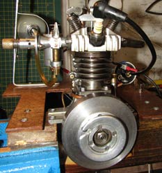
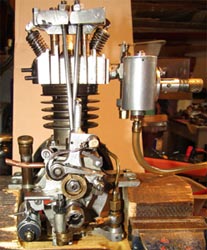
The motor is still something of a mystery as it has elements of several commercial designs, but does not follow any particular one. The radial valve gear and aluminium cylinder head is fairly advanced for the period and style of engine does not follow any known designs either, so was it made entirely 'in house'? After being removed from the hull, and stripped of carburettor, exhaust, coupling and condenser the engine was soaked in a bath of petrol and as much dirt as possible scrubbed off with a toothbrush. A bench mount was cut from an old 3" square post to clamp the engine securely to work on once I had read up and assimilated the detail needed to understand what it was all about. While doing this I set about the simpler task of cleaning up the hull. |
After stripping off the trim the surface dirt was cleaned off with meths before filling the damaged sections with wood filler. After sanding smooth an undercoat was put on that turned out to be gloss enamel and not easy to sand down. It proved difficult to fill in the cracks so numerous coats of paint were rubbed down before a satisfactory finish was achieved.
 |
 |
| Filling and rubbing down on decking | The fine result of all the work |
|
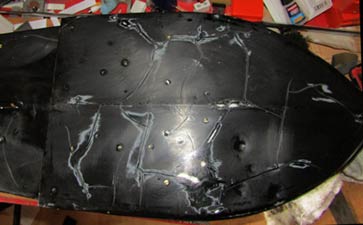
One final coat was to be applied later. The aluminium trim and cockpit coating was polished with 1200 wet and dry and the cord snubber washed in washing up liquid. The steel screws were all replaced with brass to avoid future rusting. The underside of the hull again required a great deal of filling and careful rubbing down before a suitable finish was achieved after three attempts. Photos of the underside show the sleek lines of the hull of which the original maker should have been justly proud. (a very unusual method of construction that shows an advanced level of skill and craftsmanship) With all the paintwork now finished it was back to the engine. |
|
|
|
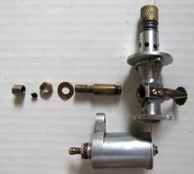
The carburettor is interesting and further suggests that the boat might have had two distinct lives. Most engines of the period, primarily intended for out and out racing, were fitted with simple stranglers to allow easy starting, but this one has a very unusual system that allows adjustment to the amount of air allowed in to the engine through a series of holes in the venturi that are progressively uncovered by a spring loaded and knurled adjuster. There seems to be no provision for flat out running at all unless the strangler is removed completely? From the style and materials used it seems likely that it was a later addition that gave control over the speed of the boat to allow free running. The almost vernier like unit can be seen at the top, attached to the flange of the venturi where a normal plate type strangler would be fitted. |
The ignition components are all commercial, the condenser and contact breaker both stamped Ford. When the coil was tested, it showed no internal connection across the primary coils and signs of a previous repair, so the solder was carefully drilled out and a brass screw screwed in to make contact with the copper strip in the coil, ensuring both primary and secondary circuits were now intact.
 |
 |
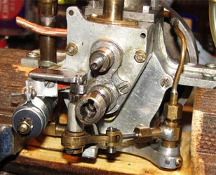 |
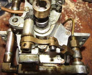
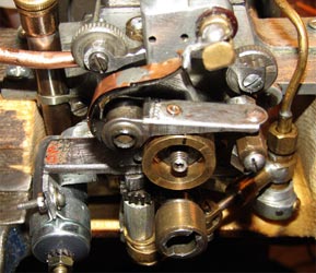
| Drive side of engine | Contact Breaker assembly | Timing chest with worm drive to oil pump |
Stripping down and cleaning the motor was halted as the flywheel steadfastly refused to budge, the oil sump was stuck firm and no apparent way of removing the two, rear cylinder head studs. Whilst waiting for advice I decided to prepare an engine test rig that would at least prove that the electrics worked OK. With the engine set up in the test rig, attempts to detect a spark from the original coil proved unpromising, leading to the conclusion that a new one was needed, but when connected up to the wiring rig, no spark, so a new condenser, but still no sparks. Whilst 'musing' over this problem I put the engine back into the hull to take some finished photos and lowered the boat into the garden pond to see that it floated OK and did not leak, but a trickle of water flowing out revealed a leak along the step, cured with a liberal application of superglue.
Dismantling the engine continued to prove difficult through the lack of clear information as to how it was all held together and seventy year old oil. The workmanship on the oil pump seemed to suggest that it is custom built whilst the big end bearing cap that was lock wired and soldered also indicates a high level of engineering?
|
|
There are a couple of ways of making new gaskets, a ball pein hammer to cut out the shape and mark the holes, or the hi-tech way that Dougal used. The sump gasket seemed to be made of a form of thin paper but I am not sure what to make a new one from. Meanwhile I traced the outline of the sump onto a piece of clear plastic sheet and scanned this into the computer. Then the image was pasted onto an MS Publisher page to scale and the mounting holes accurately marked onto the image. After punching the holes and trimming to size, the template was taped onto a sheet of gasket material, punched and cut out to make the new gasket. The oil pump is driven via worm gear on the crankshaft down to an eccentric and then to a reciprocating pump fed from the sump. More steam technology than IC? |
By 30th May I had managed to get a spark, but unsure as to why since nothing different had been done to the setup.
|
After reassembly and setting
the timing on the CB cam, new gaskets and all pipes cleaned and checked it was
ready for testing.
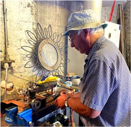
On the 29th June the engine rig was relocated to the garage, fuelled up and first attempts at starting with a cord, but to no avail, no fuel getting to the cylinder so further investigation of the carburettor required. Two months of frustration followed as every element was checked, new plug fitted, many adjustments and then with the aid of an electric starter on the 28th of August, it fired up, if only briefly. Right: Dougal with electric starter finally gets the engine started. |
|
|
After further adjustments another start proved successful, but only just long enough to get a short video clip before it stopped. It was quite noisy and a lot of smoke ensued. I decided to call it a day having proved that the engine was capable of running in its current state. However it was clear that more engineering work would be needed to bring it up to an operational condition for use in a speedboat.
 |
 |
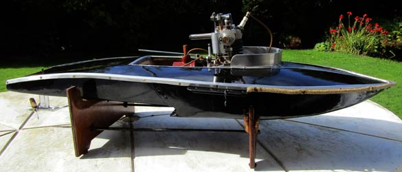 |
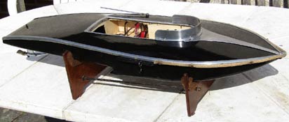
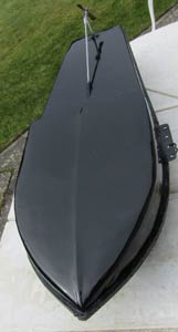
| The completed renovation showing the very sleek lines of the hull and the slipper stern | ||
©copyrightOTW/DougalMcIntyre2022