|
Home Updates Hydros Cars Engines Contacts Links ←2016 2018→ Contact On The Wire |
|
|
Oliver Monk 'Workshop Ramblings' 2017 |
January 2017
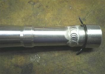
This is my NSC 2.5cc tether car, now on its fourth engine. The best speed I have managed is a few laps at 260kph with the second engine. It has been named the "British Brick" by Michael Schmutz who had had the misfortune to have horsed it on a regular basis. For the last race of the season in Tallinn I changed the pipe length, the wheel diameter and head volume plus put a new liner piston in, and I nearly forgot, a new shape head and top hat glow plug. The first run showed a bit of promise but it died when accelerating, turned out to be a glowplug seal failure. The second run was 256kph and if I hadn’t been greedy it would have done 258kph, not the best speeds but a significant step forward for me. Michael also said it horsed OK, just like it should but it’s still going to be called the brick.
 |
 |
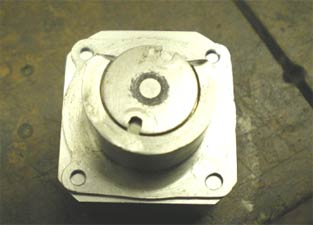
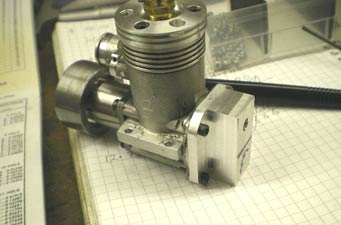
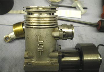
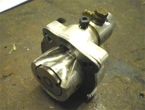
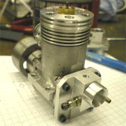
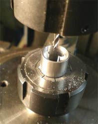
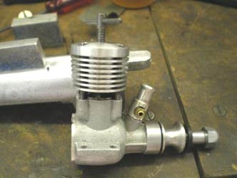
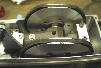
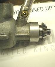
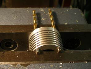
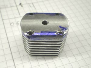
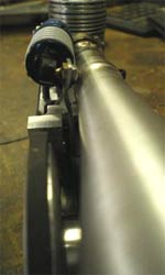
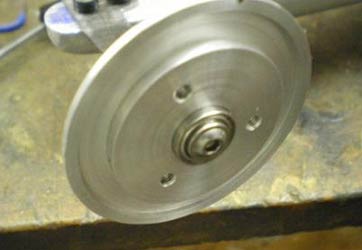
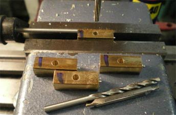
This is my second 2.5cc Stelling engine. I have wanted one for years then two turn up. This one needs a bit of remedial work as the clamp ring head has been modified, so I am making a new one as standard.
 |
 |
 |
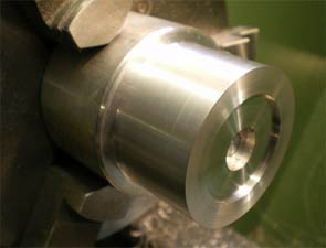
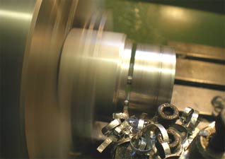
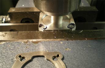
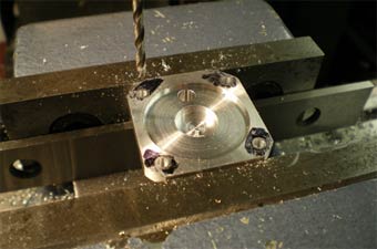
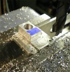
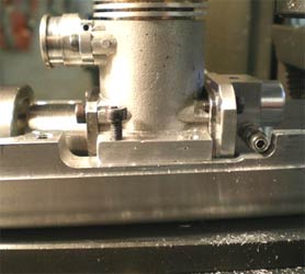
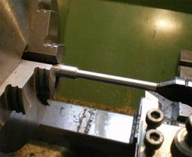
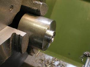
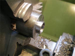
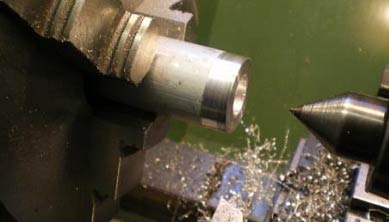
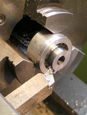
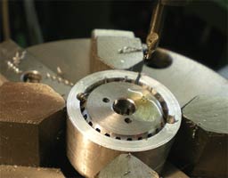
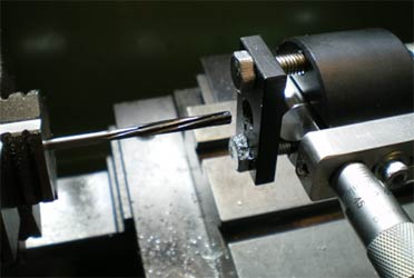
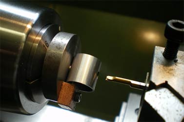
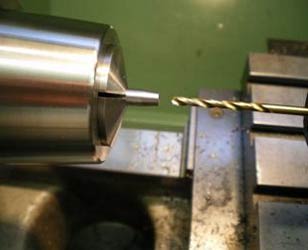
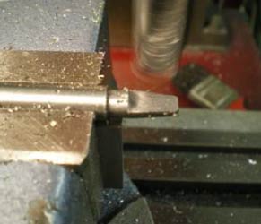
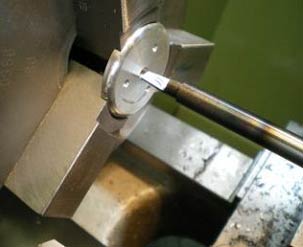
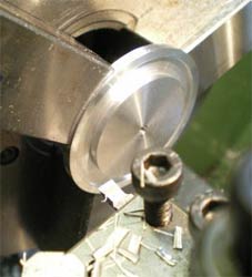
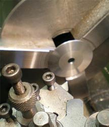
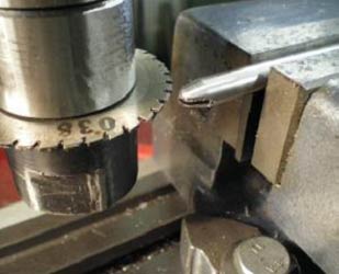
Parting off the head, then into the chuck with soft jaws. I bought a new 3 jaw chuck so I could use soft jaws. This is the second job, so much easier to hold thin parts securely. The final picture is counter boring the hold-down holes on the rotary table.
 |
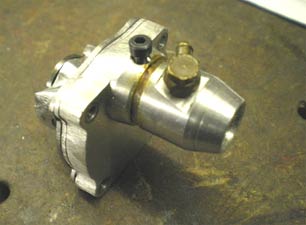 |
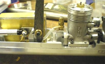
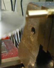
The engine came with a Zimmerman disc intake system and used a remote needle valve, unfortunately the overall length is too long and the venturi is almost touching the tank. I am told that it was made by Lothar Runkel. To make it fit the car I am going to make it shorter using a conventional needle valve assembly.
 |
 |
|
Start of
the new Zimmerman back plate |
|
 |
 |
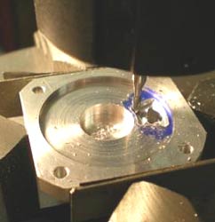
Seemed to have missed a few pictures but it was only straight forward milling. The picture on the left shows me centring up the back plate prior to coordinate drilling the mounting hole, this was the easiest way of getting the holes in right place.
|
|
|
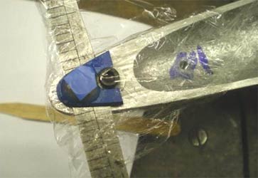
The picture above is prior to drilling the holes and on the right the new back plate and head are bolted to the engine. Some more work still to do on the back plus a new needle valve assembly.
About 14 months ago I was contacted by the Society of Model and Experimental Engineers and asked if I would do a talk on tether cars and the engineering that I do. On a Saturday at the beginning of January I went down to London by train to their headquarters, had a tour of the workshops etc. and taken for lunch at a local café. The café has a list of meeting dates so they can put on extra staff, the place was full of model engineers. The talk went well, I had taken some cars and lots of bits for them to look at; some of the members had built and run cars when they were a lot younger. Spent a quite a time talking to people afterwards apparently this is a sign of a good talk. Didn’t get any takers to run model cars though.
Well that’s it for this month only about four months to the first race in Hanover need to crack on with the second Stelling engine. For a change I am building a couple of model aeroplanes, one a control-line model from my school days and the other is a coupe de hiver rubber powered free flight model of modern construction using some carbon fibre. I am allowed to build these in the house much warmer than my workshop.
March 2017
 |
 |
 |
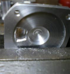
More work on the Stelling 2.5cc, continuing with the back plate, milling the intake slot and in the centre picture it's ready in the vice for blending in the two different shapes using a Dremel. On the right, Removing surplus metal from the back plate.
 |
 |
|
Installed in the car with the needle valve assembly on top of the intake. It just didn’t look right, thought it might give fuel feed problems so on with plan B. |
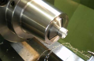
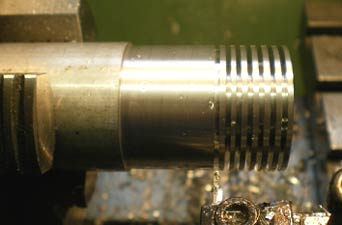
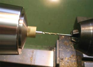
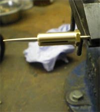
Machining up the venturi using my new 5c collet chuck. Should have bought one years ago. |
 |
 |
 |
|
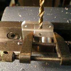
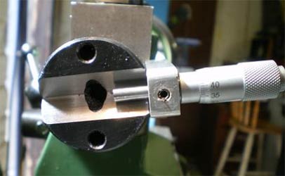
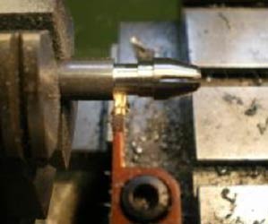
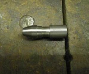
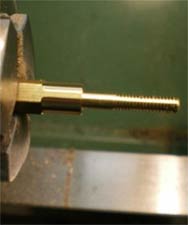
Drilling the hole ready to fit a more conventional needle valve assembly in the usual place. |
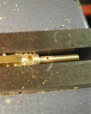
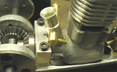
Here it is all finished, and with a bit of milling to the car's pan it now fits and an elongated hole in the body I can use this Zimmerman valve or the drum valve. I had deliberately left enough metal on the underside of the venturi to give me this option. |
|
 |
 |
|
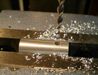
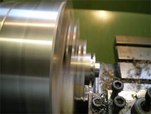
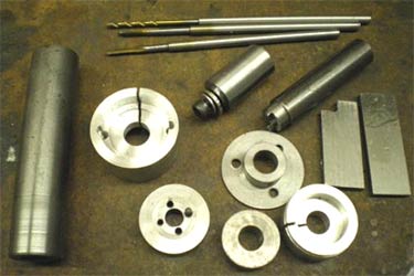
Back making piston blanks for the Stelling engine, the metal is free machining but wears the HSS tooling out quickly. For turning the bar I use a carbide inset design specially for aluminium, the drill is HSS. |
|
 |
 |
 |
|
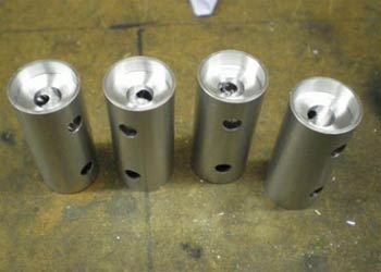
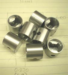
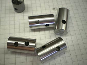
Eight pistons on the way, all gudeon pin holes drilled, ready for reaming to size. |
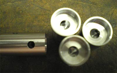
Bottom of the piston having the surplus metal milled out. |
Two pistons with the bottom all milled out by plunge milling using a carbide cutter. |
 |
 |
 |
|
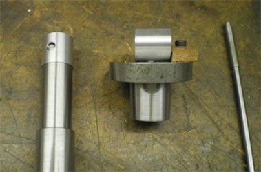
Blanks being cut in half to form 2 pistons, again a carbide tipped cutter. |
Eight new pistons |
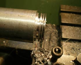
The last operation before fitting the pistons to the liners, putting in the circlip grooves. |
 |
 |
|
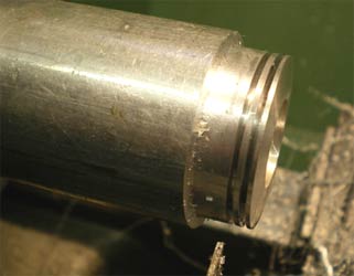
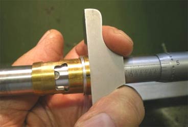
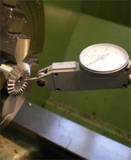
Final fitting of the piston to the liner taking tiny cuts and measuring the amount the piston moves up after every cut, so you can put the taper on the top of the piston and have enough liner left to give the required "nip". |
|
 |
 |
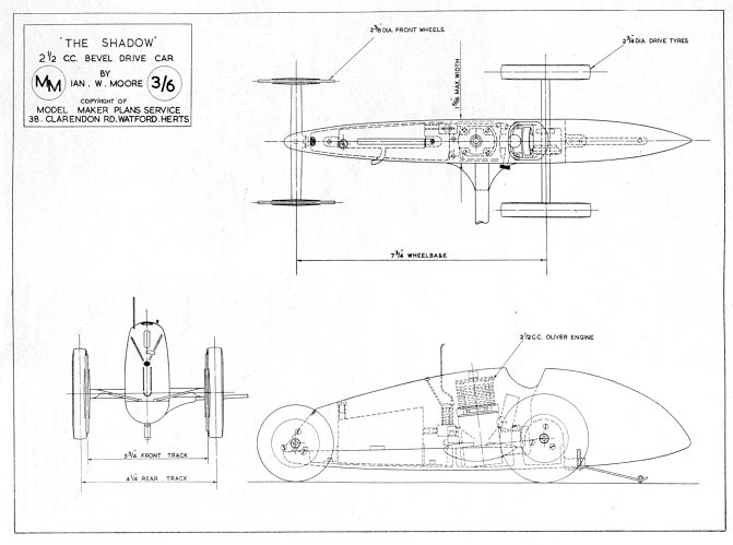
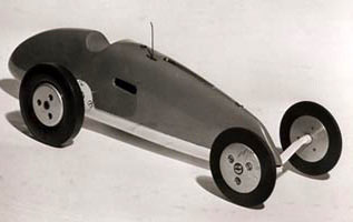
In the latest version of the Retro Racing Club's newsletter is an article on a car called the Shadow designed by Ian Moore. I had slowly been collecting all the parts to build it and they had been sitting in a drawer. The article prompted me to get the bits out. The engine is an original Oliver Tiger but needs a rebore. Also it will make a change from working on modern cars, especially pistons.
 |
 |
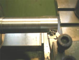
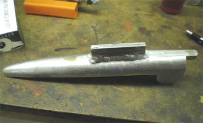
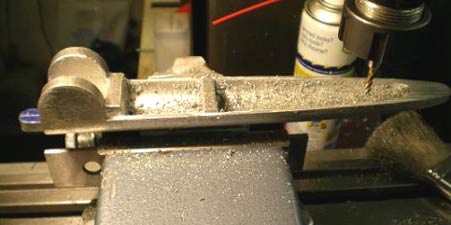
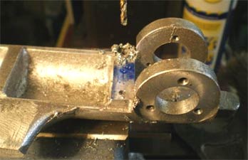
Holding the pan was going to be a challenge as there is nothing straight that I can work from, so it was down to see our local tig welder who welded on a piece of plate so I can hold it. While he was doing that I got him to weld on a new smaller diameter connector as I am modifying a 3.5cc pipe to use on my 2.5cc car.
That’s it for this month, one 2.5cc car is ready to race, the other one is close, just need to make some stingers for the pipe. The 3.5cc car needs a new piston so hopefully I will get that done before we go to Hannover for our first race this year.
April 2017
|
This was not the start I wanted to the 2017 racing season. After a day of unsuccessful training and then two rounds of the competition without a run I finally found the problem. Out of 10 glow plugs that I had bought loose one was a cold plug the rest were hot. With a plug change to a hot plug for the last round it went accelerating nicely and into the mid two hundreds, then the deathly quiet with Manu the horser slowing it down to reduce damage. Anyway more later. |
|
 |
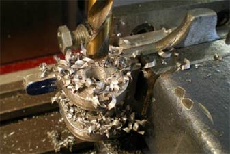 |
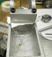
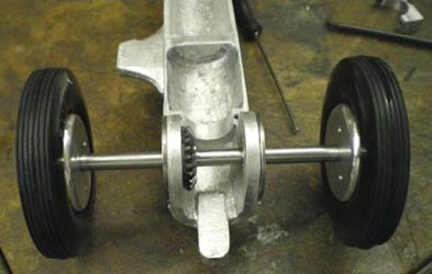
| Milling the top surface of the pan flat and the start of boring out the casting for the back axle. | |
 |
 |
 |
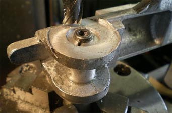
Boring out the hole for the axle bearing housing. The boring head I rescued from the scrap man when they closed the workshop at work, it’s very accurate even though it looks pretty battered and doesn’t have a name on it. The casting is not that easy to hold so I made a split mandrel to hold it to mill the housing face flat.
The third photo shows the start of machining the back axle that has a flange in the middle to bolt the crown wheel to, for some reason this is the only picture I took of the process. This end was left oversize the material pulled out for the side of the axle and all then machined to size.
 |
 |
 |
| Checking the bearing fit in the housing | The bearing housing nearly complete | Bearing housing being parted off |
 |
 |
Facing of the finished bearing housing. The rear axle assembly all complete and fitted into the pan. No pictures of drilling all the holes in the milling machine, sure you have seen enough of those?
 |
 |
Just to make things interesting the engine is held in the pan by the front housing and the back plate plus it is sloped forward 5 degrees. To get the angle right I used a thin angle block under the casting. The picture on the right shows the front engine mount, the paper is there so that when it’s finished you have a bit of clearance to tighten it down.
|
|
|
This is not the most rigid set up but it worked, the milling cutter is the only one I had that was long enough it’s a roughing cutter but the finish was OK. I had nearly finished the Ramblings and thought they all might make a bit more sense with a drawing. OTW added a couple of photos of Ian Moore's original car from an earlier article. |
 |
 |
|
|
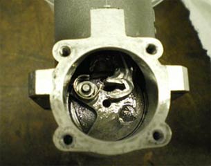
This was the damage to my 2.5cc car when the rod let go, it also bent the bottom of the liner so I could not pull the liner out through the top, it came out enough for me to saw the top off the line and get out through the bottom of the crankcase.
 |
 |
I have some new wheels on order but just in case they don’t arrive I have machined the flat off, machined a mandrel to fit the boss in the wheels and held them in place with a revolving centre, save drilling and tapping holes to hold them in place.
 |
 |
That’s it for this month I am hoping for a bit more luck in the next race at Kapfenhardt in the Black Forest, a good race and a nice social event.
June 2017
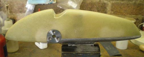
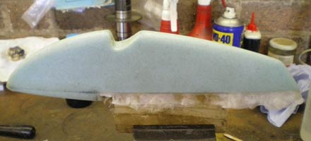
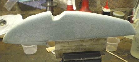
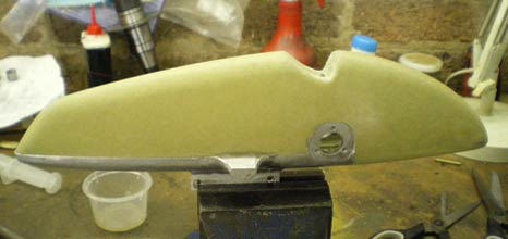
The Shadow coming along nicely. The top has proved to be a tight fit but no real problems. The fibreglass version is a lot easier to make than carving a wooden one and a lot more durable. I am sure Ian Moore would have used fibre glass if it was available when he built his car like it is now.
 |
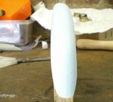 |
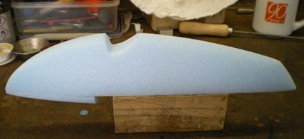
The blue foam plug prepared as close to drawing as I could get, the other picture end on, its thin.
 |
 |
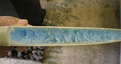
The glass I use is 28g a square metre and is bias cut i.e. at 45 degrees across the grain, this make it easy to work with. I covered the whole body with one piece of glass. First I give the plug a coat of epoxy resin then put two layers of glass on and let it cure, then rub it down until it's smooth. Another 4 layers and let it cure and rub down until smooth and so on. This body had 24 layers of glass from memory. It takes about 30 mins to rub down and put on 4 layers of glass.
 |
 |
Digging the blue foam out of the finished
part. The last few bits of foam can be washed out with solvent.
On the right, starting to fit the body to the pan.
 |
 |
 |
 |
|
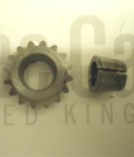
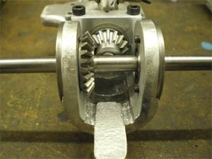
Start of the work on the gears, setting up to bore the hole in the gear to fit the axle. The other picture, the split aluminium cup to hold the gear for metal removal. |
The pinion gear with its collet to go onto the engine, the crankshaft has been shortened. |
||
 |
 |
The crown wheel having the mounting
holes drilled, and the challenge of drilling and
tapping of the mounting flange
on the axle.
 |
 |
I drilled some mild steel rod and Loctited the drill and tap in. Note the crown wheel being used as a guide for the drill. After the first hole was drilled it was tapped and the crown wheel held in place for the next two holes.
 |
 |
The gears in the chassis. Somehow I have got to get a
flywheel in there.
On the right, setting up the cylinder fins for thinning down.
 |
 |
By the time I had removed enough metal to get the top on I didn’t like the look of it so decided to make a new bit, more work to do on it.
That is as far as I have got with the Shadow this month. Got some wheels and tyres for it now. More next month.
I am not having a particularly good season with my 2.5cc cars. Have broken engines at both the race meetings I have been to. Been busy in the workshop making pistons but you’ve seen that process, I seem to have finally cracked machining the pistons to size without having to lap them. I will find out how good they are when I go to the European champs in Stryi. I should be having some new liners and pistons delivered there as a backup.
That’s it for this month, off to Hannover, last race before the European champs.
July 2017

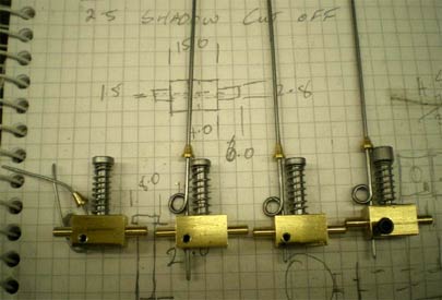
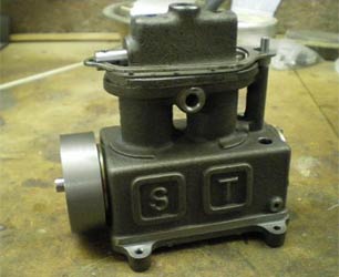
I am a member on a control line model aircraft forum. One of the topics is Engine Development so I put a picture of my timing device on. This is the one that Barrie Lever built, it’s a bit good.
Most of my time recently has been spent preparing my cars for the European Championships. I am racing one of the 2.5cc cars and my 3.5cc car, all four of the engines have had fairly major rebuilds. The gearboxes have also been stripped and cleaned and new ball races fitted.
More on pistons:-
 |
 |
One of the important things when making pistons is that the gudgeon pin hole is drilled square to the piston body. I bought a "V" block that fits into the lathe tailstock and added a micrometer to aid positioning the piston. First trials are promising.
 |
 |
A while ago I made some piston blanks for my 2.5cc motor but somehow I managed to turn them undersize. I was able to rescue some of the material to make pistons for Aaron’s 1.5cc Kapu.
 |
 |
Making 1.5cc pistons required some new tooling to be made. The first one is a mandrel to hold the piston for final machining to size, the top hat type thing is for holding the piston while machining the circlip grooves. Once this is set up it is quick and easy to do.
 |
 |
I put a steel rod through the gudgeon pin holes, and on a surface plate I check the height of each end of the rod to ensure the holes are square. The other picture shows the set up for the circlip groves. I buy the cutting tools and the smallest I can get is 0.7mm wide. For the 1.5cc engine it had to be reduced to 0.35mm wide.
|
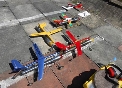
For a change Aaron and I went up the Barton Model Flying Club to see the jets fly at the speed weekend. They are fast and loud, it’s very tempting to build and fly one. Got a busy August racing cars, I doubt I am going to get much time in the workshop other than for cleaning cars. I will probably start work again on the Shadow car in September with a bit of luck. Photo by Richard Grindley |
|
October 2017

You can probably tell from the date that the picture was taken at the European championships in Stryi. The photographer was Diana, Raimondas' wife, she spends a lot of time taking pictures.
One of the things I do is record the set-up of my car and engine for every run, and the results I get from the run, good or bad, and my thoughts on maybe why it didn’t do what I expected.
At the end of the season I will record the balance of the car, the pipe length, and tank position if it’s moveable. Also the weight with fuel. On the engine I will record the exhaust timing, inlet and transfer timing, head volume and squish clearance and what liner piston it has in it. I do this because when I strip it all down for cleaning, maintenance and any improvements, come the start of the season when I want to put the cars back together I will never remember what I had done during the last season.
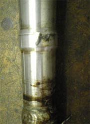
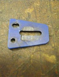
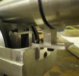
For the second half of the season I started to run the 2.5cc car that I had built, and at speed it started to make a funny rattling sound although it didn’t affect the speed. It turned out that the suspension was hitting the pipe you can’t see the missing metal. I had made the pipe support bracket out of fibre glass board that had cracked, allowing the pipe to move under the g force.
 |
 |
 |
 |
| Witness mark on pipe | GRP pipe support | New aluminium bracket | Just enough room |
The solution, a new bracket machined from aluminium with a bit more support and a bend in the suspension arm to give a bit more clearance. The bolt holding the shock absorber is not as close as it looks.
 |
 |
 |
Back on with the Shadow. The first picture shows the rear axle with a taper machined on it and about to drill and tap the end. At the same time as machining the axle I machined the taper for the "D" bit I used to cut the taper in the wheel hubs. I make my "D" bits from silver steel, they are simple to make. Machine to size then reduce the diameter to exactly half in the cutting area. Harden by heating to red hot, quench in water, clean with smooth emery and temper to straw colour then quench in water. A quick simple reamer.
 |
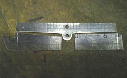 |
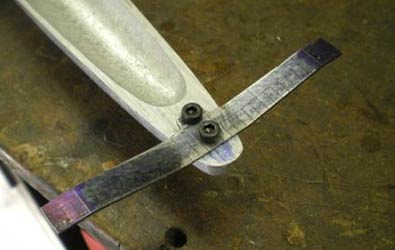
The rear wheels are on and the start of the front suspension. As you can see I have made it from a steel rule. These old rules are springy steel, perfect for the job. They can be cut, filed and drilled. For drilling, a good quality HSS sharp drill, not too fast and use cutting lubricant.
This was my last steel rule and I could do with a couple more. They are the ones that are made from carbon steel and go rusty and discoloured. Please let me know if you have any, happy to pay.
 |
 |
The front suspension on the pan and the start of the front wheels. I part them off nearly all the way through then hand saw the last bit. Why, my old mechanical hacksaw doesn’t do straight cuts.
 |
 |
 |
 |
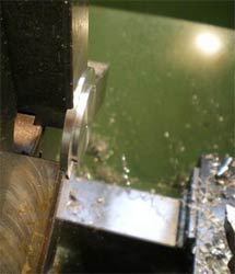
The nice thing about soft jaws is that you can hold thin bits of work easily. In the second picture, cutting the recess for the tyre bead. Machining the front and rear faces of the hubs and drilling and countersinking the holes on the fronts.
 |
 |
 |
The front wheel tyres are old 1.5cc car tyres that we were given, they are a bit big. The middle picture shows a tyre cutter, most people who race modern cars have one and mine is quite simple. The cut tyre, a bit of spit is used as a lubricant for the rubber while cutting.
 |
 |
 |
These pictures show the process of making the axles for the front wheels. They are made backwards because you cannot hold the work with the slot in the end, and you can’t hold them when they are finished to put the slot in. I don’t often use tipped tools but find this one useful, it's 2mm wide.
 |
 |
The completed front axle on the car. In the second photograph you can see the bearing sticking out from the rear hub. It is a light press fit with some Loctite to make it stay there, the outer hub locates on the bearing and is a nice sliding fit.
 |
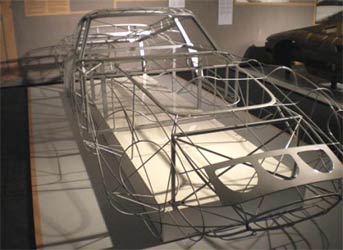 |
As well as making the car, you seem to end up making a fair few fixtures for holding the bits you want to machine and most will end up in the scrap box. During the summer I was lucky enough to visit the Ferrari museum. The wire frame is one of the first exhibits you see, made so the designers could visualise the car.
The Shadow is nearing completion, just a few more bits to make. This is the first year I don’t have a winter project lined up. I would be grateful for any ideas, thinking something old slow and not streamlined, maybe four stroke powered.
That’s it for this month, more on the Shadow next month and I need to start making pistons. Metal is on its way, but you have seen that enough times I think. Maybe a few insert heads, got a new method to try.
And don’t forget the rusty steel rules!
November 2017
Into a bit of mass production. One shut-off for the Shadow on the right and one for another project. The other two have gone to a new home, one I think is going in an Oliver Alfa Romeo. The background is one of my more detailed drawings for the cut-offs.
 |
 |
Reaming the holes in the shut-off body for the moving piston and on the other picture is machining the fuel pipe spigot. I am using my first square collet, what a wonderful thing.
After failing to find an Oliver Tiger needle valve assembly for sale on the internet I set to to make one.
 |
 |
 |
 |
| The start of the needle valve assembly | Cutting slot in the valve body | Setting the thimble | |
All straight forward machining, the mill's Digital Read Out comes in handy when drilling the holes.
To get the needle in the right place I screw the body of the needle onto the spray bar so it’s in the closed position, poke the needle in to the closed position, blow into the spray bar to check it's closed, mark the position on the needle. Then "glue" the needle in place with Loctite retainer (above right).
 |
 |
Left: The completed needle valve in the engine. The fuel pipe runs very close to the crankcase so you can get the top on. The other picture shows the front mount for the body prior to gluing the top onto it. The cling film is to stop it being permanently glued to the pan.
That’s the end of all the bits and bobs and these can be quite time consuming to make and are a real drag at the end of the build.
 |
 |
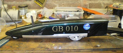
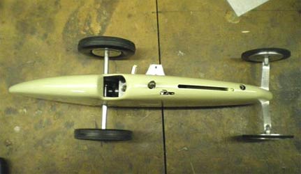
This is what the finished car looks like. My son Aaron did the painting for me, the pictures don’t really do it justice.
|
|
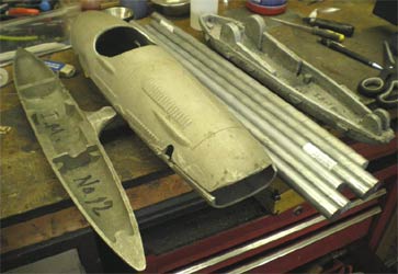
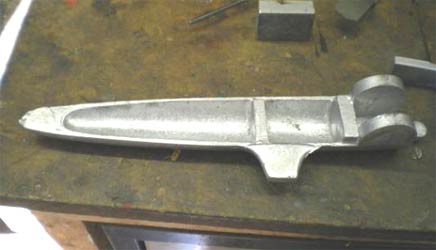
At the beginning of the month I didn’t have another project, the first to arrive was 3 metres of piston metal direct from the manufacturer in Holland. After a chance conversation I bought two Ian Moore castings and a Maserati casting which I am pretty sure is a Vega casting. The two casting on the left are my favourites to build but before I can start I need to find a set of bevel gears for the I M car and tyres for the Maserati. Any help locating either would be great.
|
Just to stop me getting bored I am building a pulse jet powered control-line model that I intend to fly in the summer and I have done some more work on the Stuart Turner flash steam engine.
 |
 |
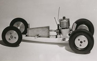
I put this picture on Facebook. It really shows the development of tether cars over the last half century or so.

That’s it for this month, the last race of the season is coming up at the beginning of December in Poland it’s going to be cold.
Not sure what’s happening in the workshop next month, got to start making pistons for both the 2.5cc and 3.5cc engines and will probably be roped in to do some 1.5cc ones as well.
PS I am not taking orders for shut offs.
©copyrightOliverMonk2017