|
Home Updates Hydros Cars Engines Contacts Links ←Previous Next→ Aircar article Contact On The Wire |
|
|
Steve Betney's Work Bench |
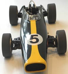
LOTUS 49: A Case of Creeping Elegance.
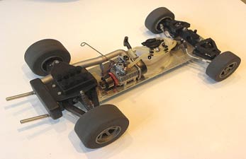
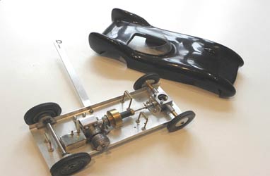
I wanted to build a more modern F1 tethered car model than my usual favourite vintage front-engine types, and decided to make a quicker scratch build by using a 1/8 scale radio controlled car rolling chassis as a base. Following a recent trip to the Castle Donington museum, I was hooked on types with big butch rear tyres and 8 upright velocity carb trumpets sticking in the air. Review of modern scale r/c cars led to the conclusion that some vintage 1970s and 80s cars had the best, simple rolling chassis 2 wheel drive types for conversion to tethered car use, but that good examples of these have become hugely collectable, with corresponding high prices. I eventually bought a Mardave Marauder rolling chassis on eBay, which had good-looking tyres. So far, so good.
|
Research on suitable F1 cars resulted in the choice of Jim Clark’s 1967 Lotus Ford 49, the last good looking car of this type before fins, aerofoils and all of those sticking out bits spoiled the lines of F1 cars’ appearance, but not traction and performance of course. A small scale 3 view drawing was located from the web, and a scaling factor worked out from the known main dimensions of the full size car. 1/8 scale would give a 12" wheelbase, which suited the Mardave chassis and wheel sizes (rear 3.5" diameter by 1.75" wide, and front 3.0" by 1.25"). The track is somewhat over-scale, though still looks reasonable. The wheels needed painting and the tyres required careful gluing to them with clear ZAP rubber toughened CA adhesive, then the tyres were sanded to run true in the lathe and their square edges rounded off for better appearance. So, we now have an outline plot for the project. |
|
|
|
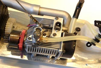
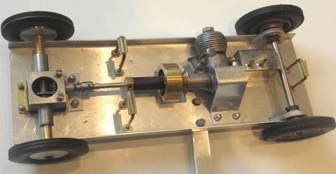
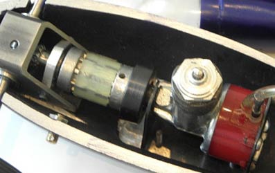
A new OS12LD car engine was to hand, which is a most interesting powerplant with a pull starter for flat mounting laid down on its side, and this is where the creeping elegance set in on the simple build. The quite nice OS black plastic engine cover was cast aside in the interests of cooling and appearance. The pull start was relatively simple to relocate by 90 degrees to a more suitable orientation, and it wasn’t an insuperable task to modify and fit a 28mm modern clutch plus flywheel assembly with a suitable spur drive gear, using a split taper collet to replace the OS prop driver. The carburettor was a more substantial issue, as the OS has a modern slide version rather than a rotary barrel type, and the orientation was 90 degrees from the desired position. Another rotary carb was found with the correct diameter stub and a vertical needle, and modified to fit by making a mounting flange, enlarging the air hole and making a knock-off arm to fit the barrel lever to use as a fuel cut out. The mounting holes for the original plastic body cover were used to affix a bracket with a power socket for a removable plug wired to a 2v starter battery to fire the glowplug. All in all, a good bit more work than hoped for. |
|
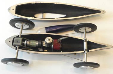
Inspection of the Mardave rolling chassis led to the conclusion that it was quite well made and a simple, budget design for its day, but a number of modifications were needed to improve application as a tethered car (what’s that creeping in here?.....). This chassis plate of 2mm aluminium has folded up edges, but was considered a bit too flimsy and wide for this project, so a new flat plate of 1/8" hard alloy was sawn to size as a substitute. This allows ½" L section ali strips to be used fixed to the inside long edges of the body sides to enable eventual easy mounting with short M3 countersunk screws from the underside of the base into Hank nuts in the strips. The Mardave front and rear steel axle shafts run directly in the moulded black nylon suspension parts, and as there was insufficient space to fit ball or roller bearings, thin- walled, sintered bronze bearing sleeves were installed. |
|
|
|
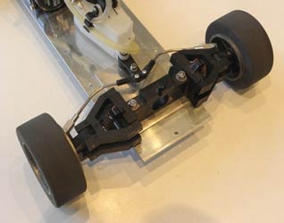
The original r/c push rods and fittings for the front steering were rather flimsy, so replacement 3mm steel rods were bent up and substantial ali fork and ball joint end fittings substituted, providing a still adjustable steering tracking arrangement to the locked centre arm. Again, all rather more additional work than originally envisaged, so the way of creeping forward was now well established. How should the 8 dummy velocity trumpets be made for the carb? The idea of turning them up in the lathe from ali bar stock was shied away from as being over-kill, and I settled instead on using some dolls house lamp reflectors with ali tube extensions and a fillet of filler, re-shaped by sanding to final curved shape in the lathe. The air shield filters were made by stretching some soft fine ali mesh material over the suitably rounded end of piece of wooden dowel, then these parts snipped to shape and epoxy glued on to the trumpet parts. A shaped piece of hard balsa forms the base into which these are fixed and screwed to the top of the rear suspension plate, representing the top part of the Ford V8 engine. |
|
By juggling and cutting some small sections of the rear LHS nylon suspension moulding and its ali top spring mounting plate, it was possible to route a piece of silver coloured 12mm internal diameter silicone tube from the OS engine’s exhaust manifold outlet through the suspension assembly to exit at the rear of the chassis. A suitable silencer was then welded up from rectangular ali box section material with a 12mm inlet tube to fit the silicone tubing, and two upswept 8mm outside diameter polished aluminium tubes for the outlets. All of these parts were sprayed with flat black epoxy paint, and I think are quite a pleasing and plausible representation of the original car (stand off scale, as aeromodellers call it). Another quite substantial amount more of work than originally envisaged on this back end for the car, but it is creeping (even if not necessarily elegantly) towards being in sight of the finish. |
|
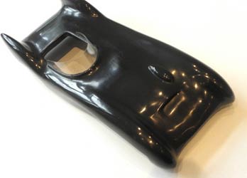
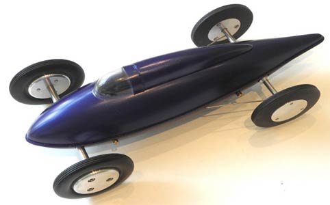
The car body was constructed as simply as possible from two side cheek profiles of ½" obechi sheet with a central block of rock hard balsa bandsawn to shape, assembled using Franklins Titebond wood glue and clamping the sandwiched parts until dry. It’s an easy enough and very satisfying task to carve, razor plane and sand this lump of wood to final external body shape, then saw out the cockpit area just a little over-scale to expose the engine compartment with access to the pull starter, needle valve, glow power socket and fuel tank filling cap. No space for a driver figure here though, unfortunately. Then a much more complex job to hollow out the body so that it fits over the rolling chassis and clears all of the suspension, power train and various internal parts and has a hollow nose part. The ½" L shaped ali side strips mentioned earlier for affixing the body to the chassis plate are epoxy glued and screwed into place on the obechi sides, then the mounting holes drilled in the chassis plate through to these and the Hank nuts installed, a much better engineered approach than just holes tapped directly into the 1/16" material of the strips. The exterior and interior of the shaped and sanded body was then given a few coats of cellulose sanding sealer, rubbed down in between, then hard skins of 2 oz flexible weave glass cloth were applied with Z Poxy resin. After sanding the glass epoxy surfaces, more sanding sealer and final rubbing down gave a surface ready for painting.
|
Not so fast, time for more mission creep! The car top looked a bit unreal with no wrap-around windscreen, so the rather difficult job of shaping and fashioning one from 1mm clear plastic sheet was undertaken by making a cardboard template by trial and error until it fitted all round. A groove was then excavated in the body top around the cockpit in which to install this with RC canopy glue, and when dry, a large fillet of Humbrol filler was added and sanded to a smooth, faired shape, then more sanding sealer used over this to get back to the ready for painting stage. Well, almost, as I then decided to add roll bars behind the cockpit, welding them up from 1/8" diameter hard ali rod. |
|
The finish chosen was BRG cellulose with a yellow central stripe down to and around the nose area, as on the original Jim Clark car. I will not bore you with the challenges that this simple-sounding job involved in a long, cold & wet weather spell, but when the very expensive artists’ low tack masking film used for painting the yellow parts keyed into the (2 days hardened) BRG cellulose finish I was not pleased at all. This was only salvaged by a few hours’ very careful work using Servisol pectin-based label removing spray, as even though this does attack cellulose a little, it removed the tacky surface film glue then acted like T-Cut polishing compound to restore the BRG to a decent finish, good enough for fuel proofing. I’ll try to remember this tip for such problems in the future. The inside of the body was finished with flat black epoxy spray paint for motorcycle exhausts.
|
|
The car was beginning to look really nice, but naked, so I decided to add Shell and Firestone logo decals and racing numbers, made on an inkjet printer using white background decal material with images grabbed from the web. Another tip for future use: I have discovered by trial and error that importing grabbed image files into MS Word enables them to be edited and manipulated to final desired size and with any desired number of repetitions laid out on the page, which saves decal material. Does anyone know a good, fool proof, fuel proof product? I’ve tried them all, spray and brushed finish, and even when a reasonable finish is eventually achieved with multiple coats it is not resistant to even 10% or so nitro content glow fuel. Don’t tell me to use a diesel engine; I do out of choice whenever I can! The model has taken about 3 times as much building time at around a couple of hundred hours than I had originally hoped due to the evolutionary design approach as it progressed (or "creeping elegance"), but I’m probably too old and inflexible to learn from this for the next project(s)......... |
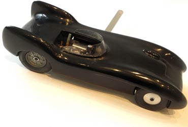
VIC SMEED LOTUS Mk IX.
|
|
Ever since I spotted a rather agricultural-looking tethered car model of a (sort of) Lotus Mk IX on eBay in the USA about 2½ years ago on sale for $1499 I quite fancied building one, then when Retro Racing Club Newsletter no.63 turned up with a picture of this on the cover and with Vic Smeed’s 1956 Model Maker plan as a feature article, I just had to go for it. Needless to say, the car didn’t sell, and neither did a rather better made, more vintage and scale but battered one with a lowly DC Sabre engine on sale for a mere £3,850 on eBay Spain a while before that. Who are these imaginative yoyos (or crooks) who pray that they might find a rich gull to part with these sorts of sums? Peter Hill kindly provided a copy of the Model Maker plan MM 434 from the RRC plans’ archive, which is up to Vic Smeed’s usual standard of clarity and accuracy, apart from one issue (see later). |
|
As I have largely followed the plan faithfully in terms of design and constructions and without modifications, I will not bore you with a detailed description of the build of the car, but just describe here some of the components used. The engine shown on the plan was an Elfin 1.49cc plain bearing diesel type, which should give a quite lively performance whether the car is built for tethered or rail track use. A decent Elfin was located, and an ED flywheel fitted the shaft taper nicely. An original, period Wreford gearbox was used for the front drive, with an appropriate, vintage flexible (but now quite age-hardened) drive coupling as shown on the plan, and then a KeilKraft 1/2A team race tank just fitted nicely between the engine and rear shaft. |
|
|
|
I fortunately had a NOS pair of vintage MRRC 2 1/8" diameter wheels with tyres to use on the rear axle, but I did add flanged ball bearings in the trunnions for less friction. RRC repro Raylite 2" tyres were used on the front drive, with turned wheel centres, as I couldn’t find any vintage MRRC types with the nice cast in spoke pattern. The one design issue I found during construction was the geometry for the mounting of the lower engine lug to the chassis pan, which is impossible as shown, unless some Elfin 1.49cc engines were made with their mounting hole centres distanced a good deal further away from the crankcase beam edges than my example (very unlikely?). The body is a glued-up sandwich of quite complex-shaped obechi slices, with the sides sections overlapping the folded ali chassis pan, and it is retained by three 1/4" Terry clips. It carves and sands into a very nice scale shape as can be seen, and the air intake, cam blister and wrap-around canopy all add to the appeal. The blister and canopy are added after finishing the carved body with sanding sealer and doped-on tissue, then sprayed cellulose primer and black lacquer is applied, then all completed with several coats of gloss fuel proofer. |
|
All in all, this is a very nice little car project with pleasing scale appearance, though there are easier subjects with simpler body shapes which would ease complexity. I quite fancy the idea of a larger version at 1/10th scale with a 2.5cc diesel – maybe one of these days? Just 2 ½ years from starting the build to finishing it is not bad by my standards. Another one off the bench! There are quite a few attractive colour schemes to choose from used on full size Lotus IXs, particularly BRG, some nice blues and even white, but I chose black as there are a couple of beautifully preserved full size examples which are still raced which caught my eye. |
|
|
Google almost any combination of the words in the title to see images of some really interesting home built cars from the USA in the immediate post-WW2 years up to the present date, built from disposable aircraft fuel tanks and using a massive variety of exotic or mundane power plants.. It is pleasurable and interesting to spend some hours reading about their history in general and some of the specific, well known cars and their drivers, and think about what nice tethered car projects they would make. Around 3 years ago some castings of around 10.5" long, c. 1/14 scale were listed on eBay UK for such a car, with a set of wheels, a fuel tank and a sprung front axle, and I got carried away in the bidding and spent far too much on winning the item. Its history is unknown, but the castings are probably a one-off of non-commercial quality and had been hacked about dreadfully, the wheels were of the wrong diameter and very poor quality, and the tank and axle were totally unsuitable for the car. I should have sent it back, but I felt rather sorry for it and was sure that something could be done with it, so I kept it. |
|
I’ve finally got round to finishing it, and whilst it’s a bit of a fat little devil, it has a certain bug-like charm. The castings had a very thick section for such a small car, so much internal excavation was in order. I selected a 1958 OK Cub 049A glow engine with its mounting cradle to power the car, as nothing any bigger would fit without the cylinder head sticking up too far above the upper body line. Internal power train layout planning indicated that it would only be possible to use front wheel drive with bevel gears. The thick bottom casting was milled flat to enable rigid mounting of the engine cradle.
|
Some of the crude excavations of the base of the body casting had to be welded up and re-finished so that a round 6mm steel axle could be used at the front with 2 ½" diameter tyres, and a non-rotating 5mm rear axle with an aluminium bar centre mounting piece could fill up the vast spaces at the rear. 2 3/8" diameter tyres were needed at the back, made up from 3" Raylite repro knife edge tyres turned down. The front tyres are some really nice Swedish vintage ones, with McCoy Mite size wheels, but I had to make up wheels with ball bearings for the rear. Robbe boat "clutches" (really heavy duty flexible couplings) are great for use on tethered cars, and one of these was used to connect the OK Cub’s flywheel to the home made bevel gearbox. The gearbox was made from drawn steel 25mm square tubing of 3mm wall thickness, using flanged bearings to support the 6mm drive axle and Muffets’ 1066 size bevel gears.
|
|
|
|
The original streamlined cast canopy fairing weighs half a ton, so a new one was carved from hard balsa wood and a clear front portion vac formed to fit, and affixed in place on the body opening with wire clips and rare earth magnets. After cleaning up the body shell halves, the insides were sprayed with black matt epoxy paint for motorcycle exhausts, then chromate etching primer followed by grey spray cellulose primer were applied to the outsides and rubbed down. Final finishing coats were of Imperial Blue gloss cellulose. Not a bad looking little car at the end of the day, to my eye at least.
|
These things can be addictive! Shortly after getting the castings for this car, I managed to get some very nice, larger 1/8 scale castings for a belly tank car from the USA, and it turned out that one of the air-cooled 10cc V6 4 stroke engines which I had made by Profi Micro Engines in the Ukraine around a decade ago was a perfect fit for these. This project has been mechanically complete for a couple of years now, so may hopefully be finished sometime soon. Here’s what it looks like now:
 |
 |
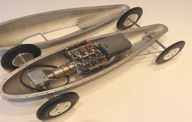
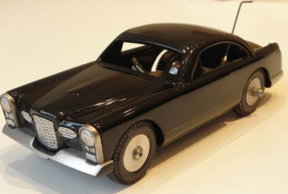
FACEL VEGA FV1 1/24 SCALE CAR
Another one off the WIP pile into finished goods, I can’t go on like this.... I bought a very nice, but rather expensive, 3 part casting set for this 1/24th scale Facel Vega FV1 car from the enthusiastic French chaps at www.jdrparis.com about 6 or 7 years ago. The website is still up, but has not been updated very recently, so the range of castings may not be still available, but do have a look anyway, as there are some very interesting cars on it. The range includes both 1/8th and 1/24th scale Facel Vega saloons, and I also have some of their other projects in my pile, the Aston Martin DBR 1 and Talbot Lago, and I finished an example of their small Jaguar D Type with a Vega 0.8cc twinshaft engine a few years ago.
 |
 |
Now, the jdrparis chaps are avid appreciators of the 1950s French Vega tethered car models, and if you can get hold of a copy of Serge Holc and Michel Molinie’s super book "Les Moteurs Reduits Francais", which has both French and English text, it contains some great coverage of this range as well as French
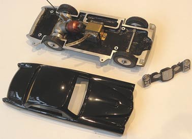
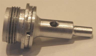
model engine history. I strongly suspect that the 1/24th scale FV1 castings were intended for 35mm Vega wheels and tyres and perhaps also the 0.8cc twinshaft engine, but this size tyre cannot be shoehorned into the castings, even with maximum excavation of the wheel wells and arches. The biggest I could get to fit were some 32mm Aeronaut tyres (actually 33mm measured on the Vernier), so perhaps there has been a design/shrinkage issue in the casting process. There is also an area on the pan casting which looks like the base for a fuel tank like the small Jaguar D type castings, but no casting for the tank itself was provided.Not being fortunate enough to be able to obtain another one of the lovely little vintage Vega 0.8cc twinshaft engines, I selected a DC Dart 0.55cc engine to power this model, as can be seen in the view of the components here. It was necessary to make a dummy shaft for this, and a crafty way of doing this not requiring screw cutting in the lathe was conceived. The image below shows the dummy shaft, which is a simple turning secured into the recess on the Dart’s backplate. I covered this in the Retro Racing Club Newsletter issue number 64 in 2016, but if you want an email copy of this just let me know at
stevebetney@aol.com and I’ll be glad to send one. A small, shielded ball bearing on the end of the shaft fits into the wheel turning to provide a free turning, non-driven side, and the finished result is shown below.
 |
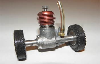 |
The engine is secured to the base pan casting using a clamp around each shaft screwed down to the base. The Dart engine I used had a damaged mounting lug, so I milled both lugs off for a neater appearance, and this also ensured that there was no lug protruding through the pan base. A small Perfect fuel tank was used ahead of the engine, secured to the pan with a brass clamp. I finished the car in black gloss cellulose, and it looks quite nice, and is a change from my usual Formula 1 subjects.
©copyrightSteveBetney2018